Optical film assembly, backlight module and display device

Active Publication Date: 2019-01-03
TCL CHINA STAR OPTOELECTRONICS TECH CO LTD
View PDF1 Cites 0 Cited by
  • Summary
  • Abstract
  • Description
  • Claims
  • Application Information

AI Technical Summary

Benefits of technology

[0008]The advantages of the present invention are: the situation is different from the prior art, the present invention provides a backlight module, including: a light source emitting a first light, a first optical film, and a second optical film laminated to the first optical film. The second optical film is a light conversion layer. The light conversion layer could enhance the light scattering to increase the light emission angle of the backlight module, such that the display device with the backlight module could achieve the wide

Problems solved by technology

That is lack of w

Method used


Image

  • Optical film assembly, backlight module and display device
  • Optical film assembly, backlight module and display device
  • Optical film assembly, backlight module and display device

Examples


Example

[0016]To provide a thorough understanding of the purposes, technical solutions, and advantages of the present invention, the present invention will be further described in detail with the accompanying drawings and the embodiments.

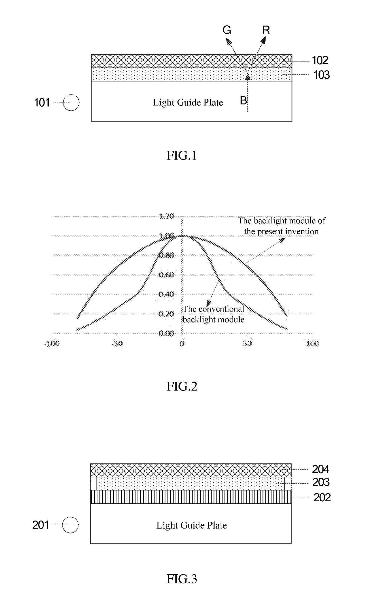
[0017]Referring to FIG. 1 and FIG. 2. FIG. 1 a schematic structural view of a backlight module in accordance with an embodiment of the present invention. The present invention provides a backlight module to provide a backlight source of the display device. The backlight module includes a light source 101, a first optical film 102, and a second optical film 103.

[0018]The light source 101 could be a point light source, a linear light source, or an area light source able to emit at least a first light. The light source 101 may include a light emitting diode (LED). The light emitting diode could emit a plurality of color lights, such as ultraviolet light or blue light. In some embodiments, the light source 101 also could be other emitting chip, etc.

[0019]The se...


PUM


Abstract

The invention provides an optical film assembly, a backlight module, and a display device. The backlight module includes a light source emitting at least a first light, a first optical film, and a second optical film laminated to the first optical film, wherein the first optical film includes a functional layer but does not include a base film, the functional layer is a diffusion film, a brightness enhancement film, a reflection film, or a prism film, and the second optical film is a light conversion layer, the light conversion layer receives the first light and converts the first light to at least a second light to emit, such that a light emission angle of the backlight module matches a requirement of wide viewing angle. The invention could broaden the light emitting angle of the backlight module to make the display device with the backlight module achieve wide viewing angle.

Description

BACKGROUNDTechnical Field[0001]The present invention relates to the technical field of liquid crystal display, and in particular to an optical film assembly, a backlight module, and a display device.Description of the Related Art[0002]Liquid crystal displays (LCD) has a small size, low power consumption, no radiation and other characteristics, has dominated the field of flat panel display. In recent years, LCD devices have been widely used such as high definition televisions, computers, laptops, mobile phones, and digital cameras and so on.[0003]The inventors of the present invention in a long-term research and development have found that the lights is directional after the backlight passed the polarizer, the TFT, and so on, wherein the most of lights vertically emit from the screen. In other words, the image would have different colors when it is watched in different positions from the liquid crystal display. The image could not display the original color in particular when it is w...

Claims


Application Information

Patent Timeline
IPC IPC(8): F21V8/00
CPCG02B6/005G02B6/0051G02B6/0053G02B6/0055G02B5/0205G02F1/1336G02F2202/36G02F1/133614
Inventor CHANG, JIANYULEE, YUNG-JUIHSIAO, YU-CHUNCHANG CHIEN, SHENG-JERSU, ZANJIAHAI, BO
Owner TCL CHINA STAR OPTOELECTRONICS TECH CO LTD
Why Eureka
Try Eureka