
Liquid crystal display device

Active Publication Date: 2008-05-08
PANASONIC LIQUID CRYSTAL DISPLAY CO LTD +1
View PDF12 Cites 3 Cited by
  • Summary
  • Abstract
  • Description
  • Claims
  • Application Information

AI Technical Summary

Benefits of technology

[0010]Accordingly, it is an object of the present invention to provide a liquid crystal display device which can overcome the above-mentioned drawbacks of the related art.
[0013]According to the present invention, it is possible to acquire a liquid crystal display device having a wide viewing angle with this simple structure without using an expensive retardation film in the VA-mode liquid crystal display panel.

Problems solved by technology

However, in the VA-mode liquid crystal display panel, there exists a drawback of a narrow viewing angle which colors the liquid crystal display panel in a specific color when viewed in an oblique direction.
However, any one of known methods is not a fundamental solution method and, particularly, the method which uses the retardation film has a drawback that the method pushes up a manufacturing cost due to the use of the expensive retardation film.

Method used


Image

  • Liquid crystal display device
  • Liquid crystal display device
  • Liquid crystal display device

Examples


Embodiment Construction

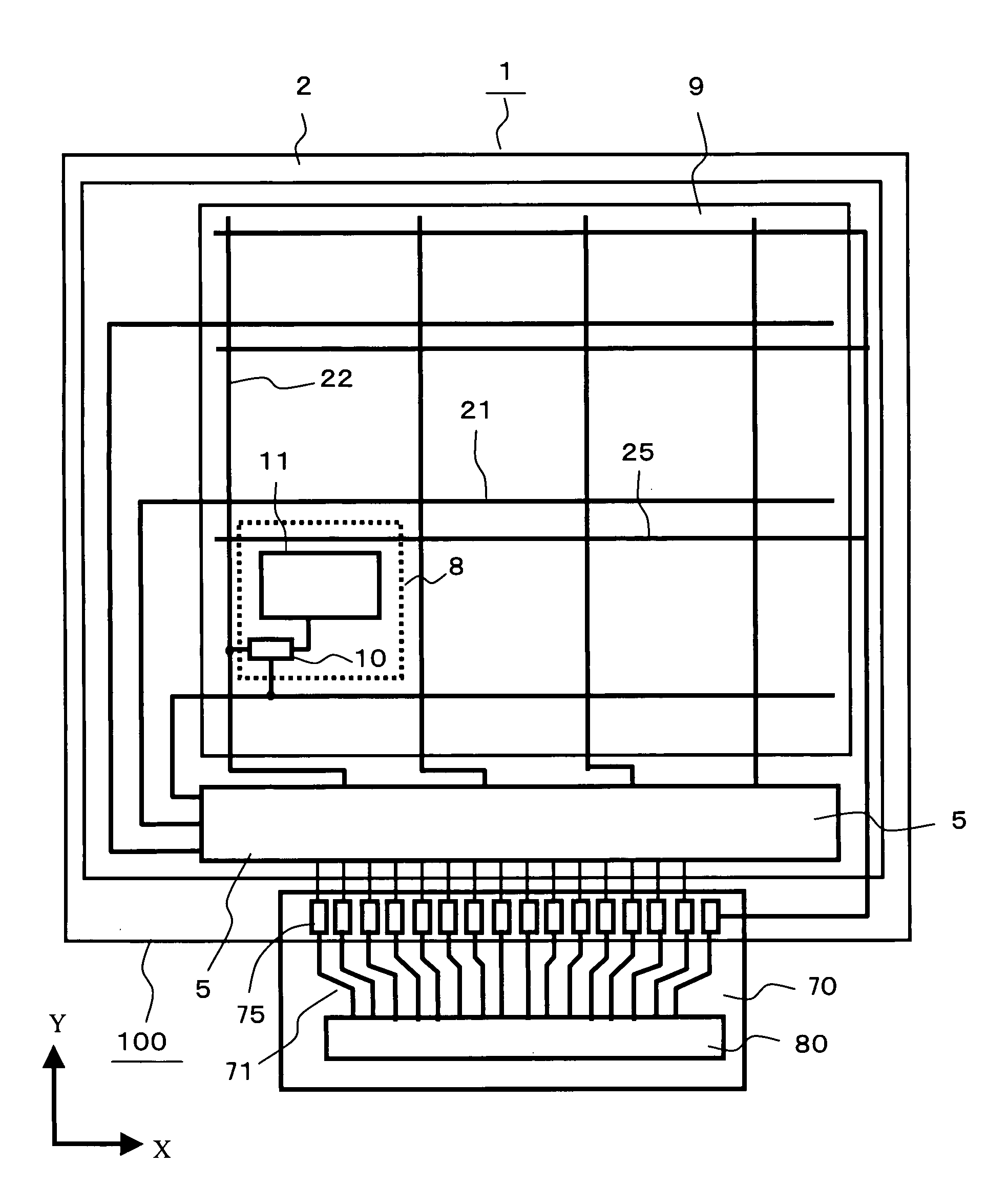
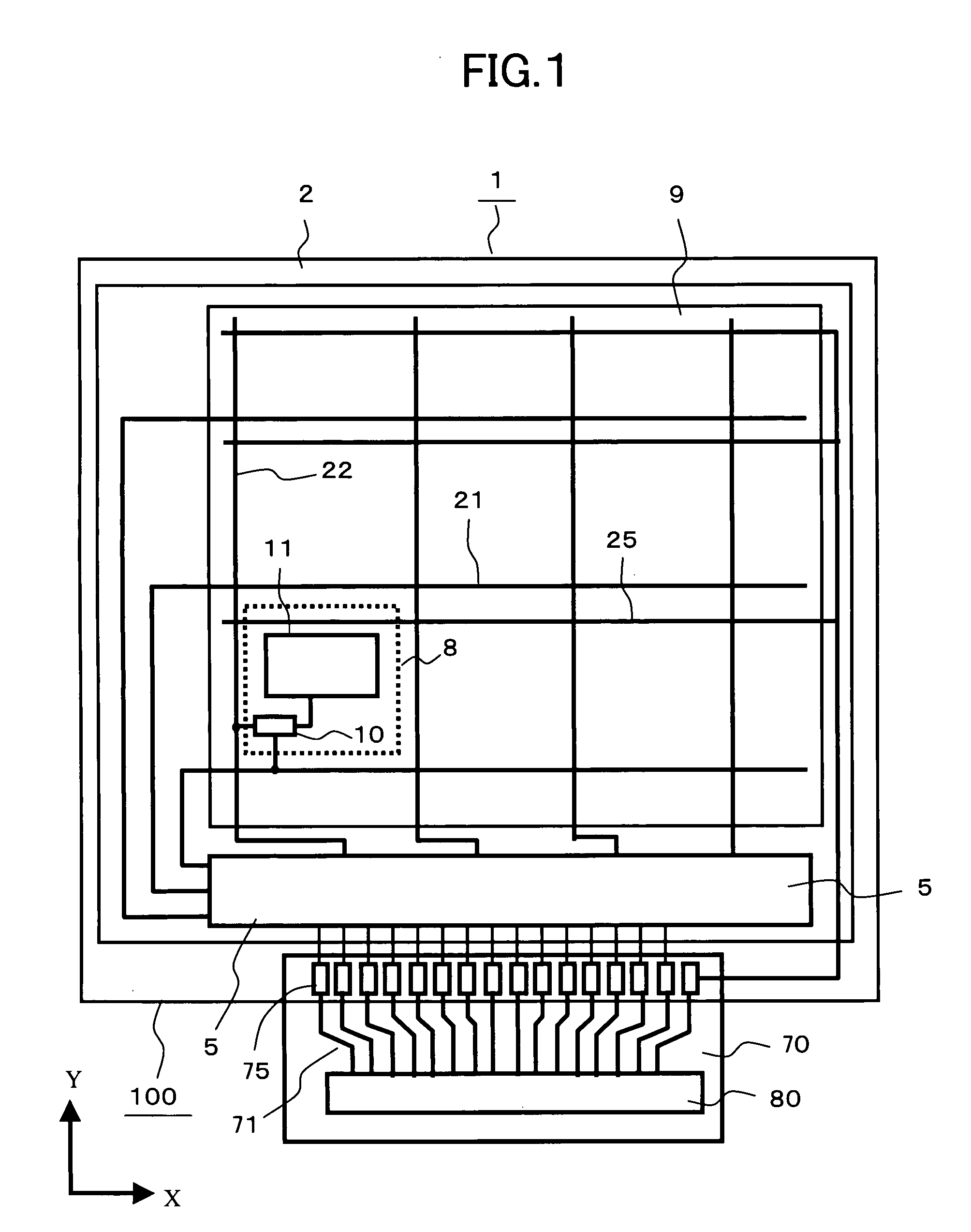
[0028]FIG. 1 is a plan view showing a liquid crystal display device 100 according to the present invention. The liquid crystal display device 100 is constituted of a liquid crystal display panel 1 and a control circuit 80. Signals necessary for a display of the liquid crystal display panel 1 are supplied from the control circuit 80. The control circuit 80 is mounted on a flexible printed circuit board 70 and transmits signals to the liquid crystal display panel 1 via lines 71 and terminals 75.

[0029]A pixel electrode 11 is formed in each pixel portion 8 of the liquid crystal display panel 1. Here, although the liquid crystal display panel 1 includes a large number of pixel portions 8 which are arranged in a matrix array, to facilitate the understanding of the pixel portion 8, only one pixel portion 8 is illustrated in FIG. 1. The pixel portions 8 which are arranged in a matrix array form a display region 9, wherein the respective pixel portions 8 play a role of pixels of an image and...


PUM


Abstract

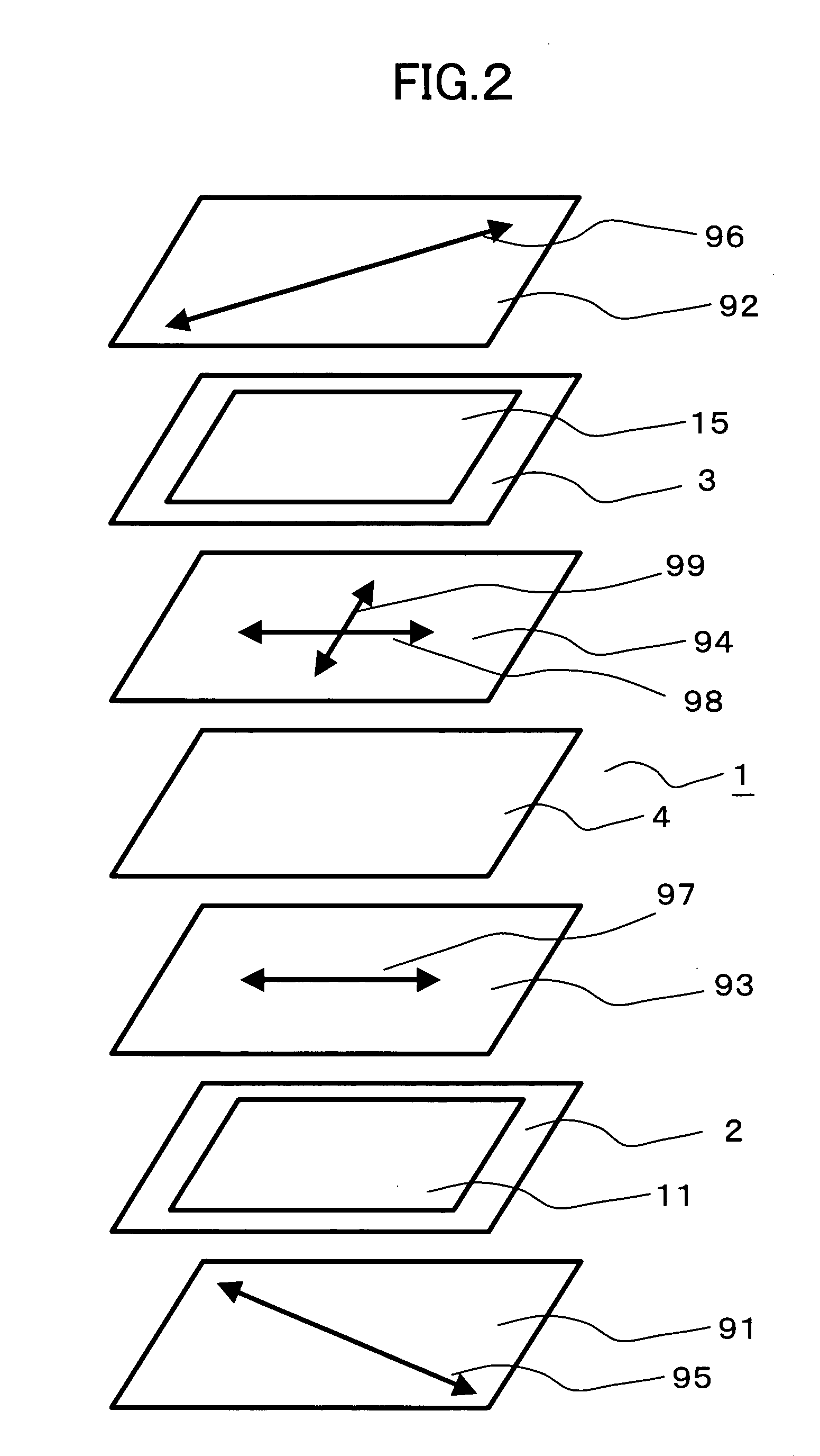
The present invention compensates for a viewing angle of a VA-mode liquid crystal display device without using an expensive viewing angle enlarging film. In a VA-mode liquid crystal display panel, by radiating light such as ultraviolet rays to a first alignment film, main chains in molecules of the alignment film are arranged to form a first slow axis. By also radiating the light to a second alignment film, a second slow axis is formed. The first slow axis and the second slow axis are arranged to cross each other. When an electric field is applied to a liquid crystal layer, liquid crystal molecules tilt in the direction which crosses the extending direction of projections formed on a substrate. The projections are formed such that the direction along which the liquid crystal molecules tilt and a first slow axis or a second slow axis differ from each other.

Description

BACKGROUND OF THE INVENTION[0001]1. Field of the Invention[0002]The present invention relates to a liquid crystal display panel and a liquid crystal display device which uses the liquid crystal display panel, and more particularly to a liquid crystal display device which is operated in a vertical alignment mode (hereinafter referred to as a VA mode) in which liquid crystal molecules are aligned in the direction approximately perpendicular to a surface of a substrate.[0003]2. Description of the Related Art[0004]Liquid crystal display devices have been popularly used as display devices for various information processing devices including personal computers, display devices for television receiver sets and the like. Among these liquid crystal display devices, a liquid crystal display device which uses a VA-mode liquid crystal display panel has been commercialized.[0005]The VA-mode liquid crystal display panel uses liquid crystal having negative dielectric anisotropy and aligns the liqu...

Claims


Application Information

Patent Timeline
IPC IPC(8): G02F1/1335
CPCG02F1/133707Y10T428/1023G02F1/1393G02F1/133788C09K2323/027
Inventor MATSUI, CHIKAESONODA, HIDEHIRO
Owner PANASONIC LIQUID CRYSTAL DISPLAY CO LTD
Learn More