

Optical system and image pickup apparatus having the same
- Summary
- Abstract
- Description
- Claims
- Application Information
AI Technical Summary
Benefits of technology
Problems solved by technology
Method used
Image

Examples
Embodiment Construction
[0021]Preferred embodiments of the present invention will now be described in detail in accordance with the accompanying drawings.
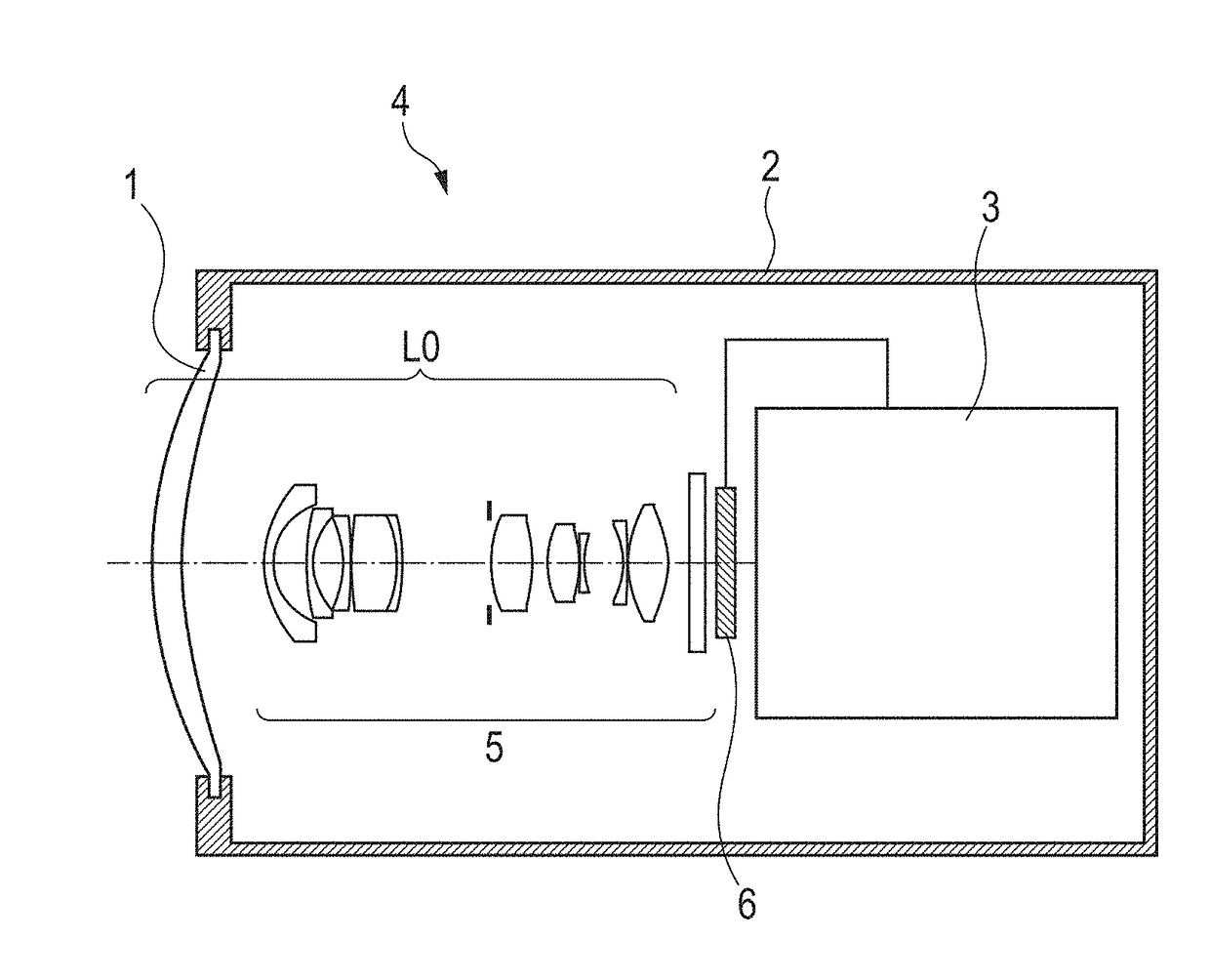
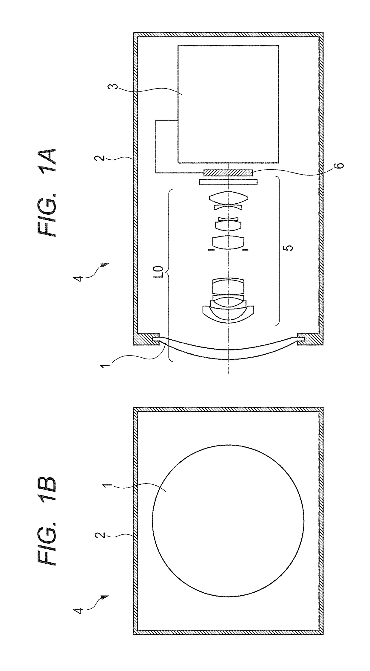
[0022]An optical system and an image pickup apparatus having the same according to the present invention will be described below. The optical system according to the present invention has a protection cover and a lens portion arranged in order from the object side to the image side. The protection cover consists of a single optical element (lens) made of resin, and at least one optical surface (lens surface) of the protection cover is an aspherical surface which continuously changes in shape from the optical axis (the lens surface apex) to the peripheral part.
[0023]The optical system used for the image pickup apparatus according to the present invention has a protection cover and a lens portion, and distortion is corrected well while achieving a wide angle of view with the entire system being small. The protection cover protects the lens portion and corre...
PUM
 Abstract
Description
Claims
Application Information