

Zoom lens and image pickup apparatus
- Summary
- Abstract
- Description
- Claims
- Application Information
AI Technical Summary
Benefits of technology
Problems solved by technology
Method used
Image

Examples
embodiment 3
[0062]In Embodiment 3, the rear lens group LR consists of, in order from the object side to the image side, a fifth lens unit L5 having a positive refractive power, and a sixth lens unit L6 having a negative refractive power. In each of Embodiments, it is preferred to satisfy one or more of the conditional expressions provided below. A focal length of the rear lens group LR at the wide-angle end is represented by fRw, and a focal length of an entire system of the zoom lens at the wide-angle end is represented by fw. A focal length of the lens system IS for image stabilization is represented by f4S. A focal length of the first lens unit L1 is represented by f1, a focal length of the second lens unit L2 is represented by f2, and a focal length of the third lens unit L3 is represented by f3.
[0063]At this time, it is preferred to satisfy one or more of the following conditional expressions:
−0.1
2.0
1.0<−f1 / fw<2.0 (3);
1.0
1.0<−f3 / fw...
embodiment 1
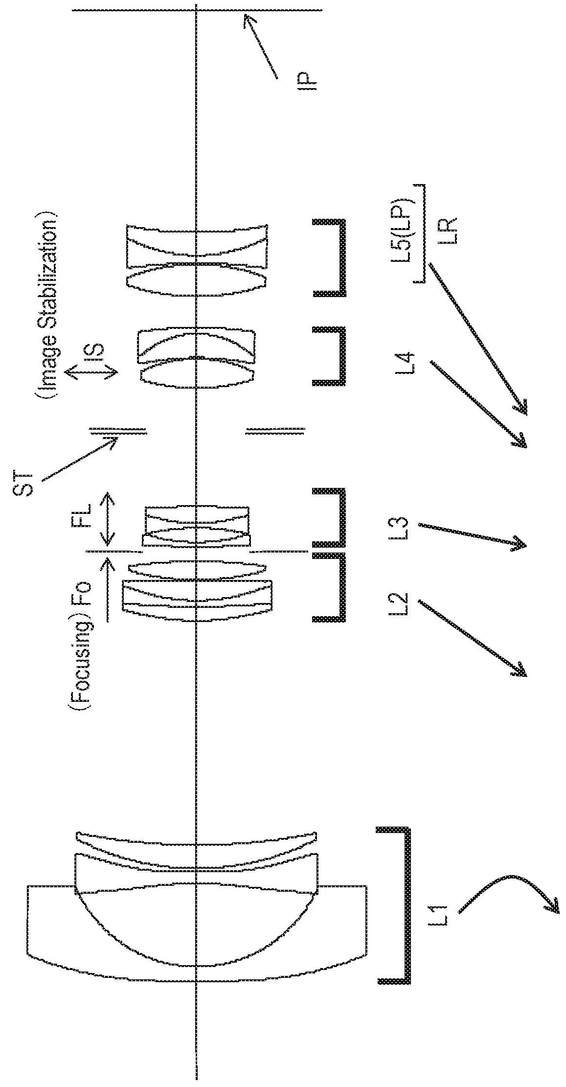
[0079]Now, a configuration in each of Embodiments is described. Embodiment 1 relates to a five-unit zoom lens consisting of, in order from an object side to an image side, a first lens unit L1 having a negative refractive power, a second lens unit L2 having a positive refractive power, a third lens unit L3 having a negative refractive power, a fourth lens unit L4 having a positive refractive power, and a fifth lens unit L5 (lens unit LP) having a positive refractive power, the zoom lens having an image pickup angle of view at the wide-angle end of 102.38°, and a zoom ratio of 3.91.
[0080]The second lens unit L2 is configured to move toward the image side over the entire zoom region during focusing to effectively obtain the focusing sensitivity. Moreover, the third lens unit L3 is configured to move toward the image side near the wide-angle end, and toward the object side near the telephoto end during focusing. As a result, the variation in curvature of field is corrected on the wide-...
embodiment 2
[0084 relates to a six-unit zoom lens consisting of, in order from an object side to an image side, a first lens unit L1 having a negative refractive power, a second lens unit L2 having a positive refractive power, a third lens unit L3 having a negative refractive power, a fourth lens unit L4 having a positive refractive power, a fifth lens unit L5 having a negative refractive power, and a sixth lens unit L6 (lens unit LP) having a positive refractive power, the zoom lens having an image pickup angle of view at the wide-angle end of 102.38°, and a zoom ratio of 3.91.
[0085]The fourth lens unit L4 and the sixth lens unit L6 are configured to move so as to reduce the interval therebetween during zooming from the wide-angle end to the telephoto end, to thereby increase a difference in incident height of the off-axial ray on the fourth lens unit L4 and the sixth lens unit L6 at the wide-angle end, and easily reduce the diameters of the entire system. Configurations and optical actions of...
PUM
 Abstract
Description
Claims
Application Information