Method and system for using the waste heat of a computer system

Inactive Publication Date: 2009-05-07
KONIG CHRISTOPH
View PDF13 Cites 24 Cited by
  • Summary
  • Abstract
  • Description
  • Claims
  • Application Information

AI Technical Summary

Benefits of technology

[0003]One object of the invention is to devise a method and a system that use the waste hea

Problems solved by technology

Taken together, this results, first, in an enormous primary energy demand (power consumption) for larger computer systems and,

Method used


Image

  • Method and system for using the waste heat of a computer system
  • Method and system for using the waste heat of a computer system
  • Method and system for using the waste heat of a computer system

Examples


Embodiment Construction

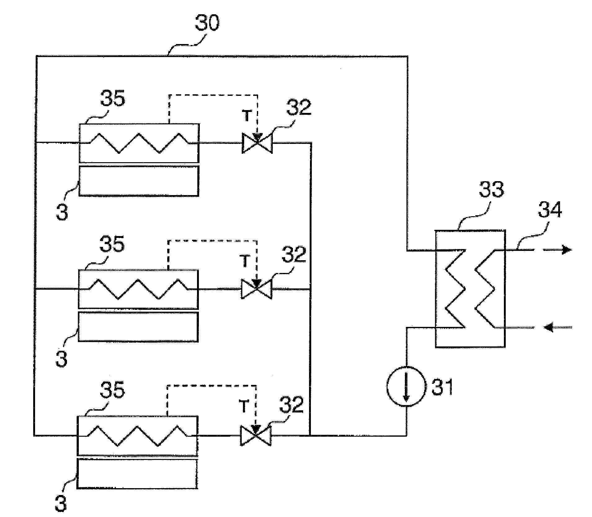
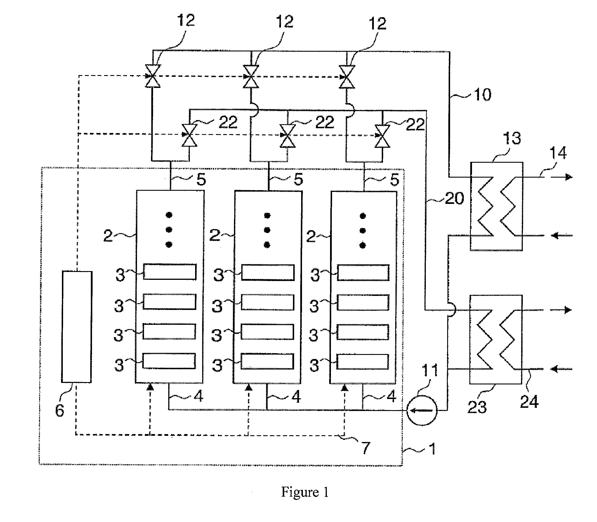
[0019]FIG. 1 shows schematically a computer system 1 that has a plurality of servers each with one or more processors 3 in several server cabinets 2. Furthermore, in the computer system there is a scheduler 4 for distributing jobs to the processors 3 of the computer system 1. The scheduler 4 is connected via a management network 5 to the processors of the computer system 1. Each server cabinet 2 is attached via a coolant inlet 6 and a coolant outlet 7 to a coolant circuit 10 with a coolant pump 11, valves 12, and a heat exchanger 13. The heat exchanger 13 thermally couples the coolant circuit 10 to a utilization circuit 14. In addition, another coolant circuit 20 is provided that is similarly connected to the server cabinets 2. The other coolant circuit 20 has an additional coolant pump 21, additional valves 22, and an additional heat exchanger 23. The additional coolant circuit 20 is thermally coupled via this additional heat exchanger to an additional utilization circuit 24. For c...


PUM


Abstract

A method for using the waste heat of a computer system with a plurality of processors comprises the following steps. Jobs in the computer system are distributed to the processors in such a way that processors of a first group of processors are operated with a high processor load and processors of a second group of processors are operated with only a minimal processor load. In another method, waste heat is dissipated from the processors by a cooling device, wherein the waste heat dissipated from the processors is regulated in such a way that the processor assumes a temperature that is greater than a given minimum temperature. In both cases, the waste heat of the processors is transferred to a device for using the waste heat.

Description

BACKGROUND OF THE INVENTION[0001]The invention relates to a method and a system for using the waste heat of a computer system with a plurality of processors.[0002]Modern computer systems, for example, so-called server farms, can have up to a few thousand processors. In light of an increasing demand for network services, it is foreseeable that the number of processors in future systems will continue to rise. With increasing performance of the individual processors, their demand for electrical power also increases. Taken together, this results, first, in an enormous primary energy demand (power consumption) for larger computer systems and, second, in a large amount of generated heat that must be transported out of the computer system via suitable cooling devices. Frequently, for the dissipation of heat out of the computer system, additional primary energy is required, for example, through the use of compressor air-conditioning systems for climate control of the rooms in which the comp...

Claims


Application Information

Patent Timeline
IPC IPC(8): F24H9/00F25B27/00H05K7/20
CPCG06F1/20H05K7/20836H05K7/20827
Inventor KONIG, CHRISTOPH
Owner KONIG CHRISTOPH
Why Eureka
Try Eureka