

Miniature zoom lens
- Summary
- Abstract
- Description
- Claims
- Application Information
AI Technical Summary
Benefits of technology
Problems solved by technology
Method used
Image

Examples
first preferred embodiment
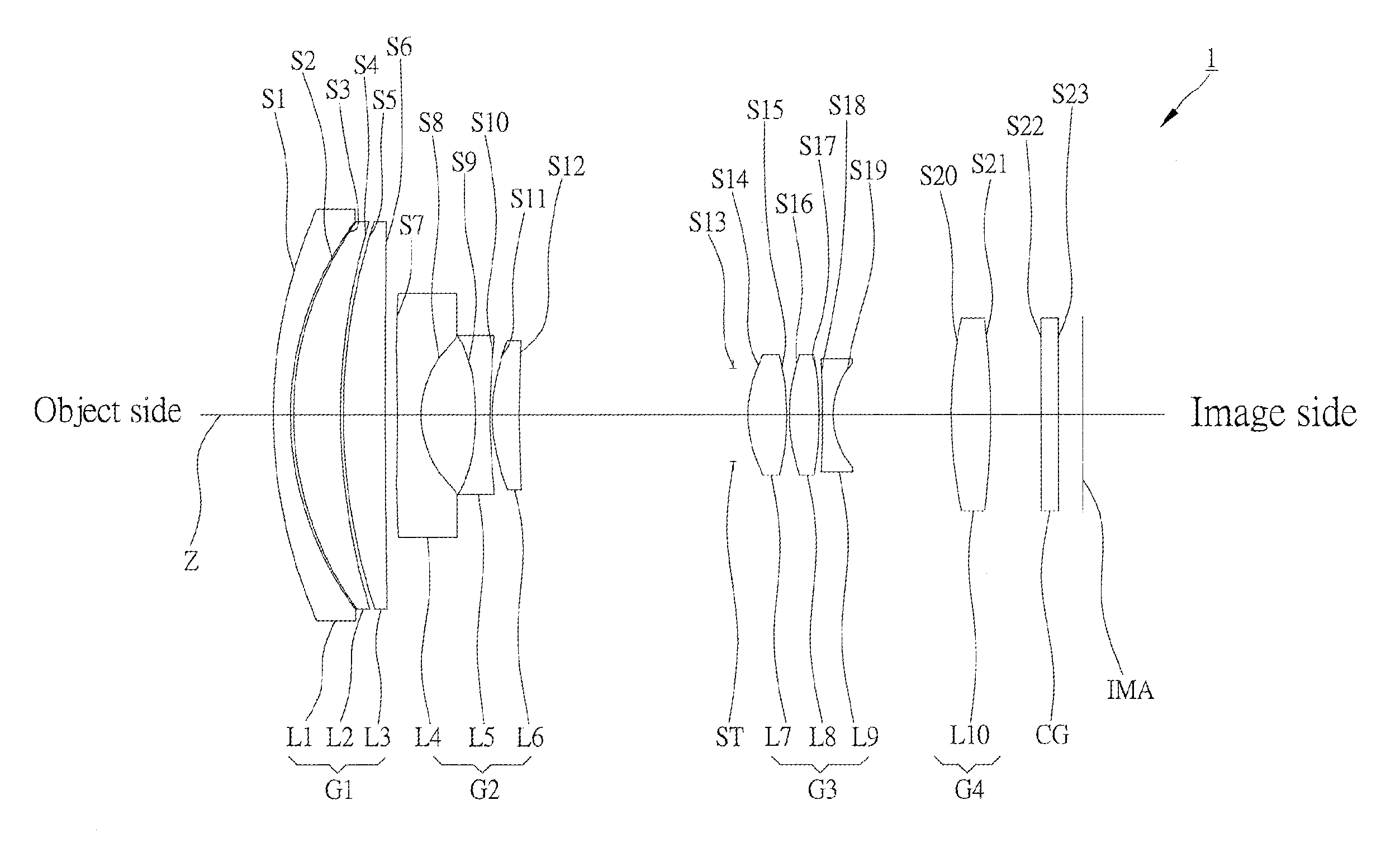
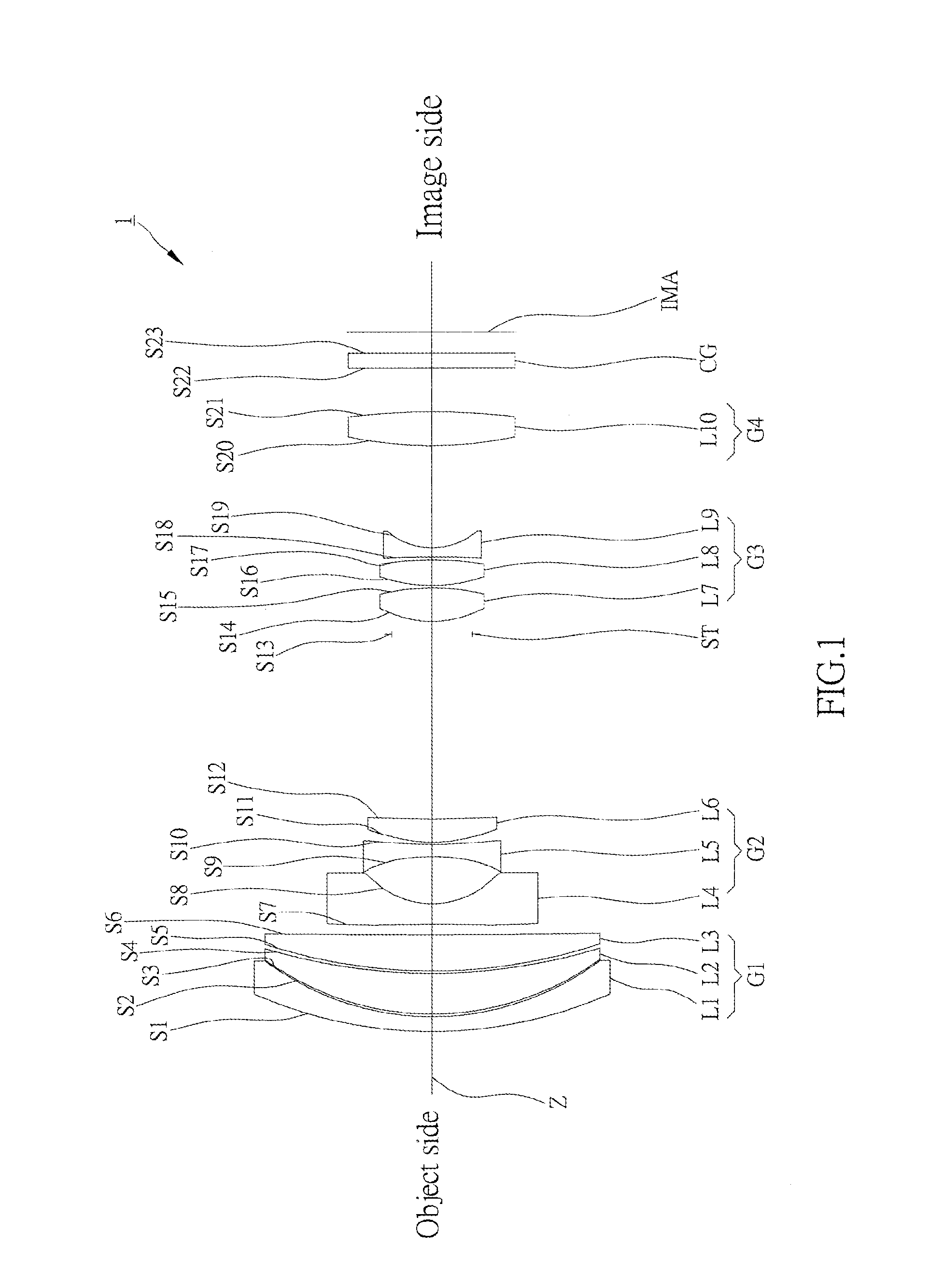
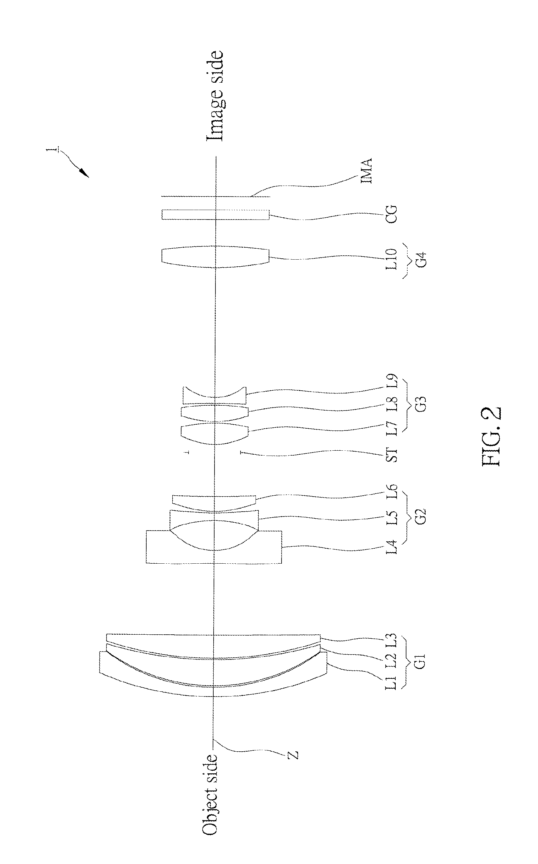
[0069]As shown in FIG. 1 to FIG. 3, a zoom lens 1 of the first preferred embodiment of the present includes, along an optical axis Z from an object side to an image side, a first lens group G1, a second lens group G2, an aperture ST, a third lens group G3, a fourth lens group G4, and an image surface IMA. The zoom lens 1 may be switched to a wide-angle mode (FIG. 1), a middle mode (FIG. 2), and a telephoto mode (FIG. 3) by moving the first lens group G1, the second lens group G2, and the third lens group G3. It may be further provided with a cover glass CG, which is a flat glass in the present embodiment, between the fourth lens group G4 and the image surface IMA.
[0070]The first lens group G1 has positive refractive power and includes a first lens L1, a second lens L2, and a third lens L3 in sequence from the object side to the image side. The first lens L1 is a meniscus lens with negative refractive power, and its convex surface S1 faces the object side. The second lens L2 is a men...
second preferred embodiment
[0100]As shown in FIG. 7 to FIG. 9, a zoom lens 2 of the second preferred embodiment of the present invention includes, along an optical axis Z from an object side to an image side, a first lens group G1, a second lens group G2, an aperture ST, a third lens group G3, a fourth lens group G4, and an image surface IMA. The zoom lens 2 may be switched to a wide-angle mode (FIG. 7), a middle mode (FIG. 8), and a telephoto mode (FIG. 9) by moving the first lens group G1, the second lens group G2, and the third lens group G3. It may be further provided with a cover glass CG, which is a flat glass in the present embodiment, between the fourth lens group G4 and the image surface IMA.
[0101]The first lens group G1 has positive refractive power and includes a first lens L1, a second lens L2, and a third lens L3 in sequence from the object side to the image side. The first lens L1 is a meniscus lens with negative refractive power, and its convex surface S1 faces the object side. The second lens ...
third preferred embodiment
[0131]As shown in FIG. 13 to FIG. 15, a zoom lens 3 of the third preferred embodiment of the present invention includes, along an optical axis Z from an object side to an image side, a first lens group G1, a second lens group G2, an aperture ST, a third lens group G3, a fourth lens group G4, and an image surface IMA. The zoom lens 1 may be switched to a wide-angle mode (FIG. 13), a middle mode (FIG. 14), and a telephoto mode (FIG. 15) by moving the first lens group G1, the second lens group G2, and the third lens group G3. It may be further provided with a cover glass CG, which is a flat glass in the present embodiment, between the fourth lens group G4 and the image surface IMA.
[0132]The first lens group G1 has positive refractive power and includes a first lens L1, a second lens L2, and a third lens L3 in sequence from the object side to the image side. The first lens L1 is a meniscus lens with negative refractive power, and its convex surface S1 faces the object side. The second l...
PUM
 Abstract
Description
Claims
Application Information