Speckle reduction with transparent blocks

a technology of transparent blocks and specks, applied in the field of coherent radiation sources, can solve the problems of further reducing the coherence level of the output beam compared to that of the input beam, etc., and achieves the effect of reducing the coherence level of the light output, reducing the coherence level of the output beam, and reducing the effect of speckl

Active Publication Date: 2006-03-30
APPL MATERIALS ISRAEL LTD
View PDF13 Cites 14 Cited by
  • Summary
  • Abstract
  • Description
  • Claims
  • Application Information

AI Technical Summary

Benefits of technology

[0010] Each of the first sub-beams is incident on the second coherence-reducing component, which comprises a second array of transparent second elements. The second elements receive different respective second portions of each of the first sub-beams, cause the second portions to traverse at least two different optical lengths generated by the second elements, and output the second portions as respective second substantially collimated sub-beams. Arranging the two components in series multiplies the coherence-reducing effect of the components, and so significantly reduces the coherence level of the light output from the second component, compared to the coherence level of light entering the first component.
[0011] A light combiner may be provided to combine the second sub-beams and output the combination as one, typically collimated, output beam. By combining a number of sub-beams which have traversed different optical lengths, the apparatus further reduces the coherence level of the output beam compared to that of the input beam, and so reduces the effect of speckle.

Problems solved by technology

By combining a number of sub-beams which have traversed different optical lengths, the apparatus further reduces the coherence level of the output beam compared to that of the input beam, and so reduces the effect of speckle.

Method used


Image

  • Speckle reduction with transparent blocks
  • Speckle reduction with transparent blocks
  • Speckle reduction with transparent blocks

Examples


Embodiment Construction

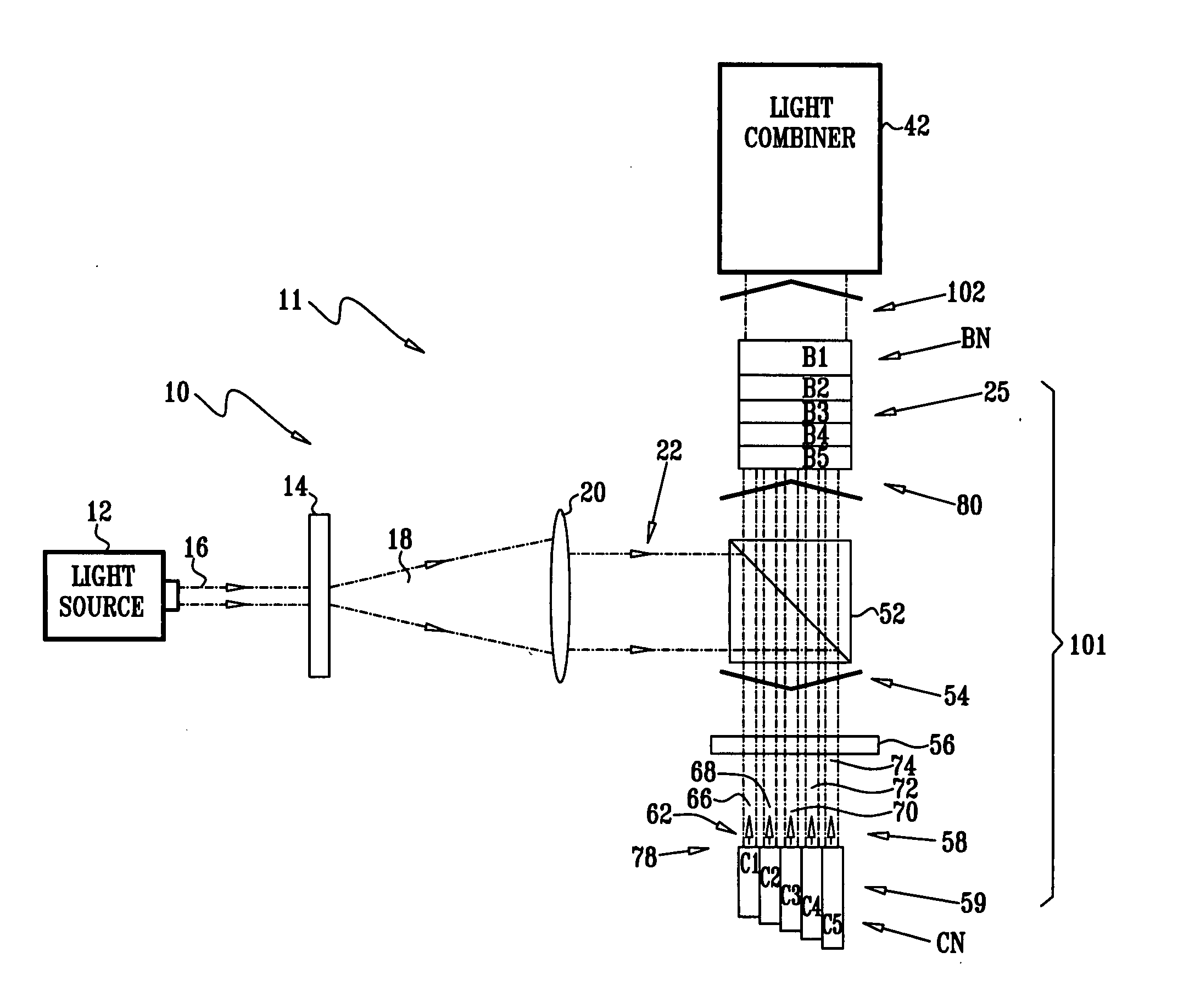
[0027] Reference is now made to FIG. 1, which is a schematic diagram of an initial section 10 of a speckle reduction apparatus 11, according to an embodiment of the present invention. A light source 12, such as a laser, emits a substantially coherent light beam 16; as is explained herein, apparatus 11 reduces the coherence level of the light. Depending on the source, light beam 16 may comprise a plurality of modes, i.e., the beam may be a multi-mode beam, or alternatively, beam 16 may be a single mode beam. Except where otherwise stated, by way of example beam 16 is herein assumed to be a multi-mode beam generated by multi-mode source 12. Beam 16 has a coherence length cL, which also depends on source 12, and which by way of example is assumed to be approximately 1 mm. Those skilled in the art will be able to adapt the following description, mutatis mutandis, for beams having values of cL different from 1 mm, and / or for single mode sources and beams.

[0028] A diffuser 14 diffuses be...


PUM


Abstract

Apparatus for reducing speckle, including a first coherence-reducing component, having a first array of transparent first elements arranged to receive different, respective first portions of a collimated light beam that is incident on the first component, the first elements generating different, respective optical lengths with respect to the light beam passing therethrough and outputting the respective first portions as respective first collimated sub-beams. The apparatus further includes a second coherence-reducing component, having a second array of transparent second elements arranged to receive different, respective second portions of each of the first collimated sub-beams of the light beam, the second elements generating different, respective optical lengths with respect to the light beam passing therethrough and outputting the respective second portions as respective second collimated sub-beams. The apparatus also includes a light combiner, which is arranged to combine the second collimated sub-beams into a collimated output beam.

Description

CROSS-REFERENCE TO RELATED APPLICATIONS [0001] This application claims the benefit of U.S. Provisional Patent Application 60 / 613,894, filed Sep. 27, 2004, which is incorporated herein by reference.FIELD OF THE INVENTION [0002] The present invention relates generally to coherent radiation sources, and specifically to reduction of speckle caused by the sources. BACKGROUND OF THE INVENTION [0003] Coherent light scattered by reflection or transmission from a rough surface forms an interference pattern in the space away from the rough surface. On viewing the pattern, an eye sees dark and light in a granular pattern, which is the speckle. An intensity detector of an optical system will also detect the speckle, and a measure of the speckle, termed its contrast, is typically a function of the ratio of the root mean square of the intensity fluctuation to the mean intensity. The varying intensity caused by the speckle may impact unfavorably on measurements made with coherent sources such as l...

Claims


Application Information

Patent Timeline
Patent Type & Authority Applications(United States)
IPC IPC(8): G01B11/02
CPCG02B27/48
Inventor KORNGUT, DORONGUETTA, AVISHAY
Owner APPL MATERIALS ISRAEL LTD
Why Eureka
Try Eureka