Antenna device

a technology of antenna array and antenna, which is applied in the direction of rhombic antenna, individually energised antenna array, non-resonant long antenna, etc., can solve the problems of difficulty in mounting on small-sized wireless apparatuses, inconvenient mounting on notebook-pc wireless terminals or fixed wireless apparatuses attached to ceilings, and deteriorating transmission quality

Inactive Publication Date: 2006-04-06
PANASONIC CORP
View PDF16 Cites 14 Cited by
  • Summary
  • Abstract
  • Description
  • Claims
  • Application Information

AI Technical Summary

Benefits of technology

[0009] An object of the present invention is to provide an antenna device, which may be suitably mounted on any of small wireless apparatuses and forms a primary beam, of which horizontally-polarized wave or vertically-polarized wave tilts toward the horizontal plane.

Problems solved by technology

In wideband wireless communications through, for example, a wireless LAN system, such a problem has arisen that the quality of transmission is deteriorated due to multi-path fading or shadowing, especially in indoor applications.
The conventional Yagi-Uda slot array planar multi-sector antenna aforementioned, however, has such a problem that it is difficult to mount on small size wireless apparatuses because the dimension of its plane incorporating six sectors is large and furthermore, the sectors need to be placed so that they may draw a circle.
Besides, the conventional end-open diamond-shape antenna aforementioned, of which primary beam advances in the direction perpendicular to the antenna plane, thereby does not tilt horizontally, has such a problem that it may not suitably mounted on the notebook-PC type of wireless terminal or the fixed wireless apparatus attached to the ceiling.

Method used


Image

  • Antenna device
  • Antenna device
  • Antenna device

Examples


embodiment 1

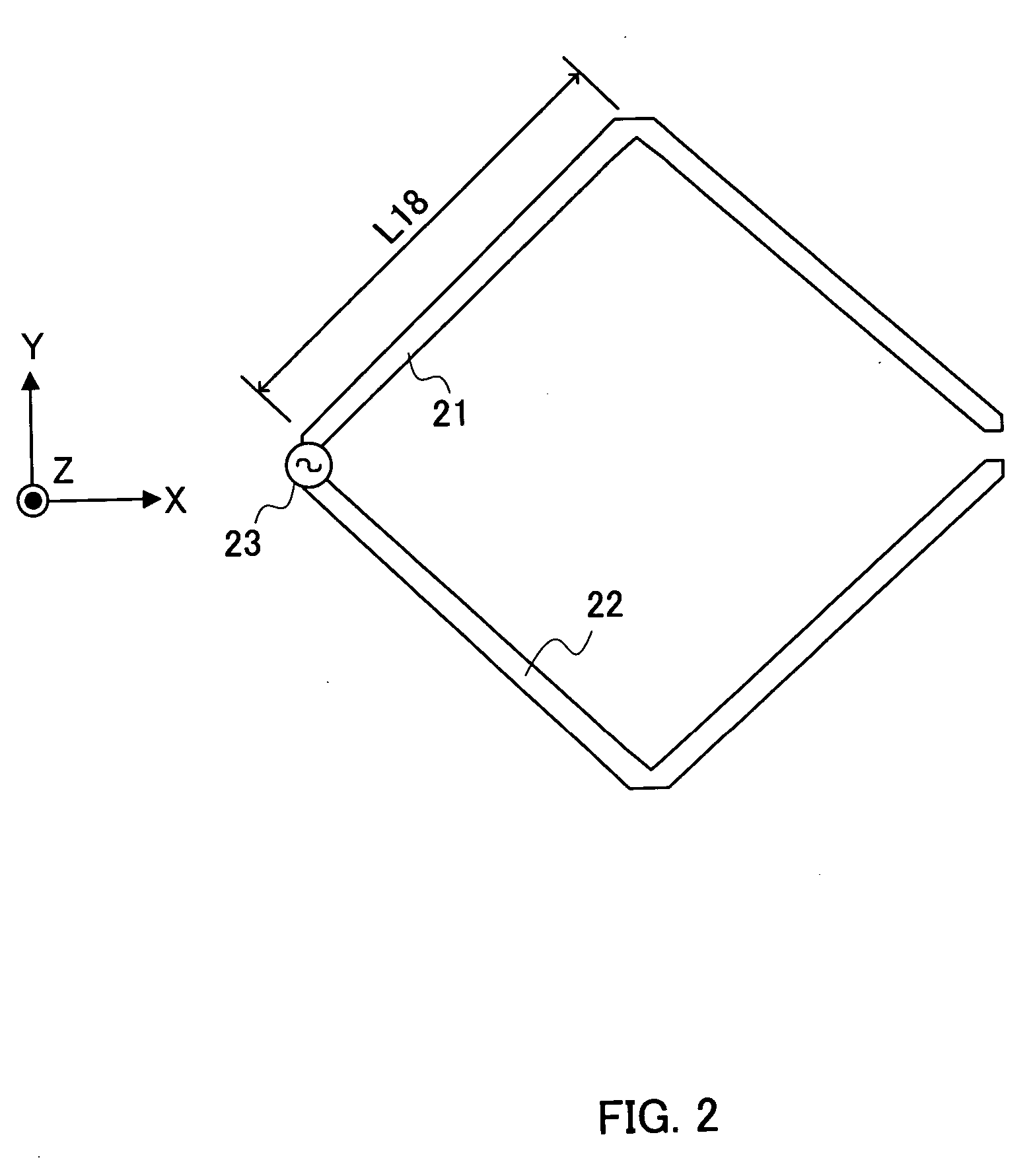
[0031]FIG. 3 is a view showing the configuration of an antenna device according to an embodiment 1 of the present invention. In the following paragraphs, the configuration of the antenna device according to the embodiment 1 is mentioned, assuming that the operating frequency of the antenna is 5 GHz.

[0032] Linear elements 101a to 101d are conductors having an element length L1 equivalent to half a wavelength (30 mm) and an element width, for example, 1 mm. These linear elements 101a to 101d are placed so that they may draw a diamond shape together as shown in FIG. 3.

[0033] In the figure, delay elements 102a and 102b are conductors, which have been bent at a point equivalent to one eighth wavelength (7.5 mm), have a total length equivalent to one fourth wavelength (15 mm) and an element width of 1 mm, wherein a length L2 indicates the length of one of their longitudinal sides. The linear elements 101a and 101c are connected one another via the delay element 102a, while the linear el...

embodiment 2

[0053]FIG. 7 is a view showing the configuration of an antenna device according to the embodiment 2 of the present invention. Note that the same portions in FIG. 7 as those in FIG. 3 have the symbols identical to those in FIG. 3 to omit their detailed descriptions. Only one difference between FIGS. 3 and 7 is in that a director element 501 has been added in the latter. The embodiment 2 is mentioned below assuming that the operating frequency of the antenna is 5 GHz.

[0054] In FIG. 7, the director element 501 is a conductor having a length L5 equivalent to 0.46 wavelength (27.6 mm) and a element width of 1 mm. The direct or element 501 is placed at a distance L6 (1 mm) from the tips of the linear elements 101c are 101d along the X-axis.

[0055]FIGS. 8A and 8B are views showing the directivity of the antenna device according to the embodiment 2 of the present invention. In FIG. 8A, a directivity 601 indicates the directivity of the horizontally-polarized wave (Eφ) component on the vert...

embodiment 3

[0059] In the embodiment 3, an antenna device, in which the linear elements of the antenna device mentioned in the embodiment 1 have been replaced with slot (gap) elements.

[0060]FIG. 9 is a view showing the configuration of the antenna device according to the embodiment 3 of the present invention. Note that the same portions in FIG. 9 as those in FIG. 3 have the symbols identical to those in FIG. 3 to omit their detailed descriptions. The embodiment 3 is mentioned below assuming that the operating frequency of antenna is 5 GHz.

[0061] In FIG. 9, a substrate 701 is a dielectric with a dielectric constant εr of, for example, 2.6 and a thickness of 1.6 mm, wherein the effective wavelength (λe) on the substrate 701 is equivalent to 84% of the wavelength (λ0) in a free space. This means that a relationship may be established between both the wavelengths; λe=0.84λ0. For this reason, the effective wavelength (λe) is used to explain the embodiment 3 below. The length L11 of each side of th...


PUM


Abstract

Linear elements 101a to 101d are conductors, which have the element length equivalent to half a wavelength, have been placed so that they may draw a diamond shape. Delay elements 102a and 102b are bent conductors, which have a total length equivalent to one fourth wavelength and a length L2 equivalent to one eighth. The linear elements 101a and 101c are connected one another via the delay element 102a, while the linear elements 101b and 101d are connected one another via the delay element 102b. A feeding section 103 is connected to each of the ends of the linear elements 101a and 101b for feeding power to them. Between the tips of the linear elements 101c and 101d, a gap with a length L3 is left. A reflector 104 has been placed at a distance h from a diamond-shape antenna with delay elements along the −Z axis, the distance h being equivalent to 0.42 wavelength. This achieves the antenna device, which may be suitably mounted on any of small wireless apparatuses and form a primary beam, of which horizontally-polarized wave or vertically-polarized wave tilts toward the horizontal direction.

Description

TECHNICAL FIELD [0001] The present invention relates to an antenna device used in mobile communications, which may be suitably applied to, for example, fixed wireless apparatuses and wireless terminals configured in a wireless LAN system. BACKGROUND ART [0002] In wideband wireless communications through, for example, a wireless LAN system, such a problem has arisen that the quality of transmission is deteriorated due to multi-path fading or shadowing, especially in indoor applications. For this reason, it is required to develop a directive antenna mounted on a wireless apparatus capable of being controlled so that a primary beam radiated from it may advance toward any direction to maintain the quality of transmission at a moderate level even in a poor radio-wave propagation environment affected by multi-path fading or shadowing. [0003] In addition, it is further required that an antenna, which is mounted on a notebook-PC type of terminal wireless apparatus for using on a desk or on ...

Claims


Application Information

Patent Timeline
Patent Type & Authority Applications(United States)
IPC IPC(8): H01Q13/10H01Q9/16H01Q9/26H01Q11/06H01Q11/12H01Q11/14H01Q13/16H01Q19/10H01Q21/08
CPCH01Q9/265H01Q11/06H01Q11/14H01Q13/16H01Q19/10H01Q21/08
Inventor SAITO, YUTAKAUNO, HIROYUKIOTA, GENICHIROHARUKI, HIROSHI
Owner PANASONIC CORP
Why Eureka
Try Eureka