

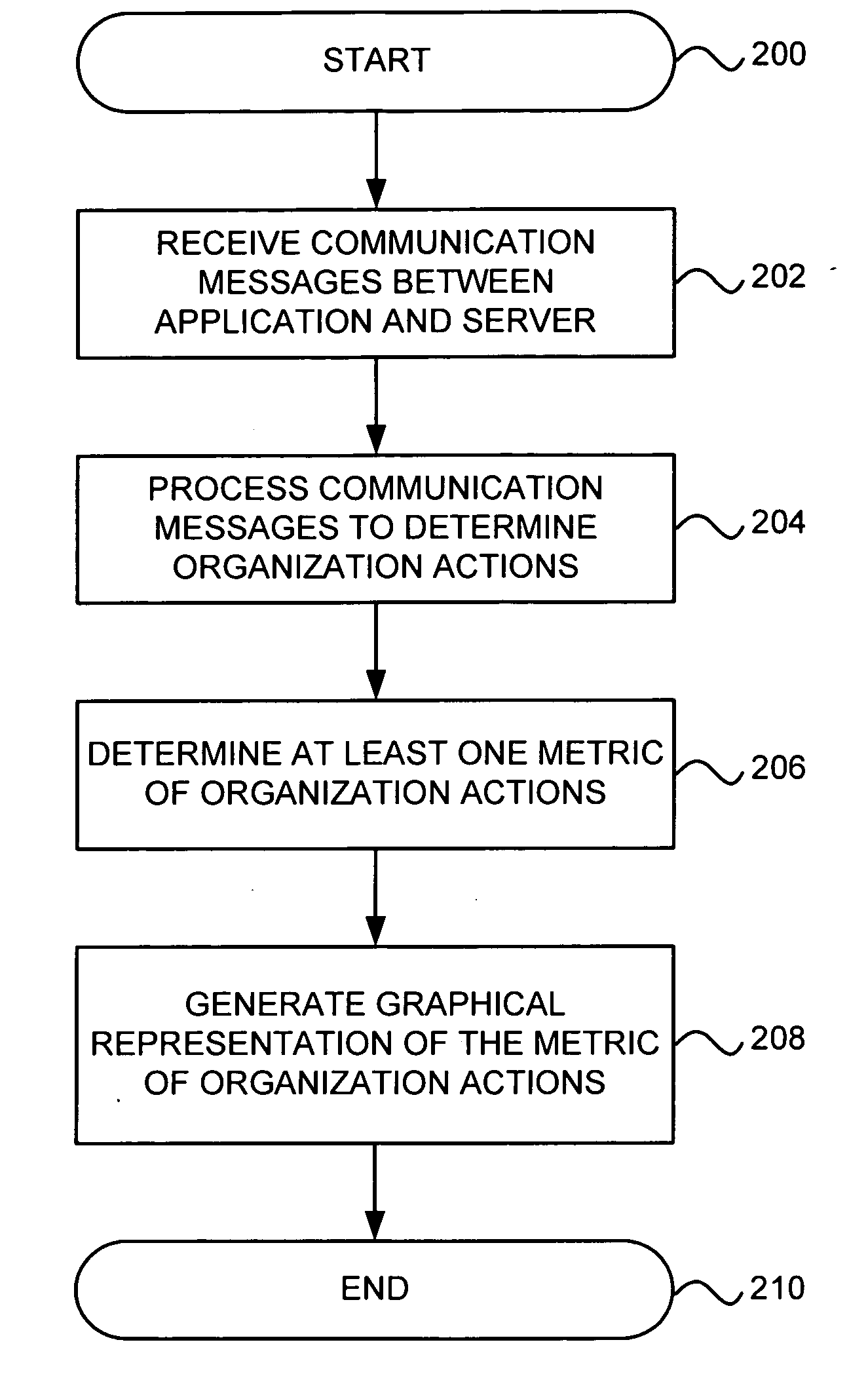
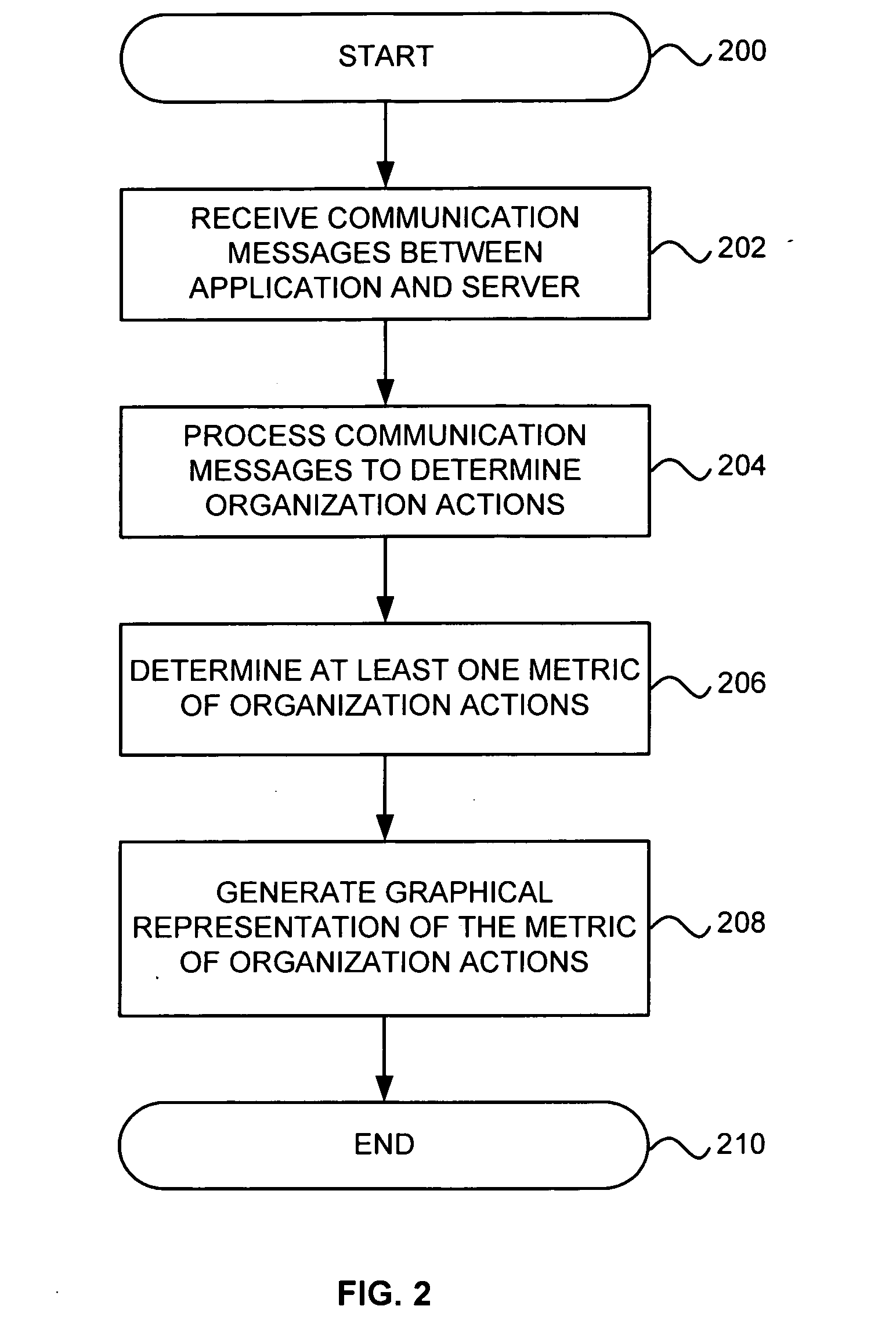
Graphical representation of organization actions
a technology of organization actions and graphs, applied in the field of graphs of organization actions, can solve the problems of affecting affecting the compliance of the administrator user, and the difficulty of reporting, so as to achieve the effect of maintaining compliance, analyzing the operation of the application and the server, and facilitating monitoring and analysis
- Summary
- Abstract
- Description
- Claims
- Application Information
AI Technical Summary
Benefits of technology
Problems solved by technology
Method used
Image

Examples
Embodiment Construction
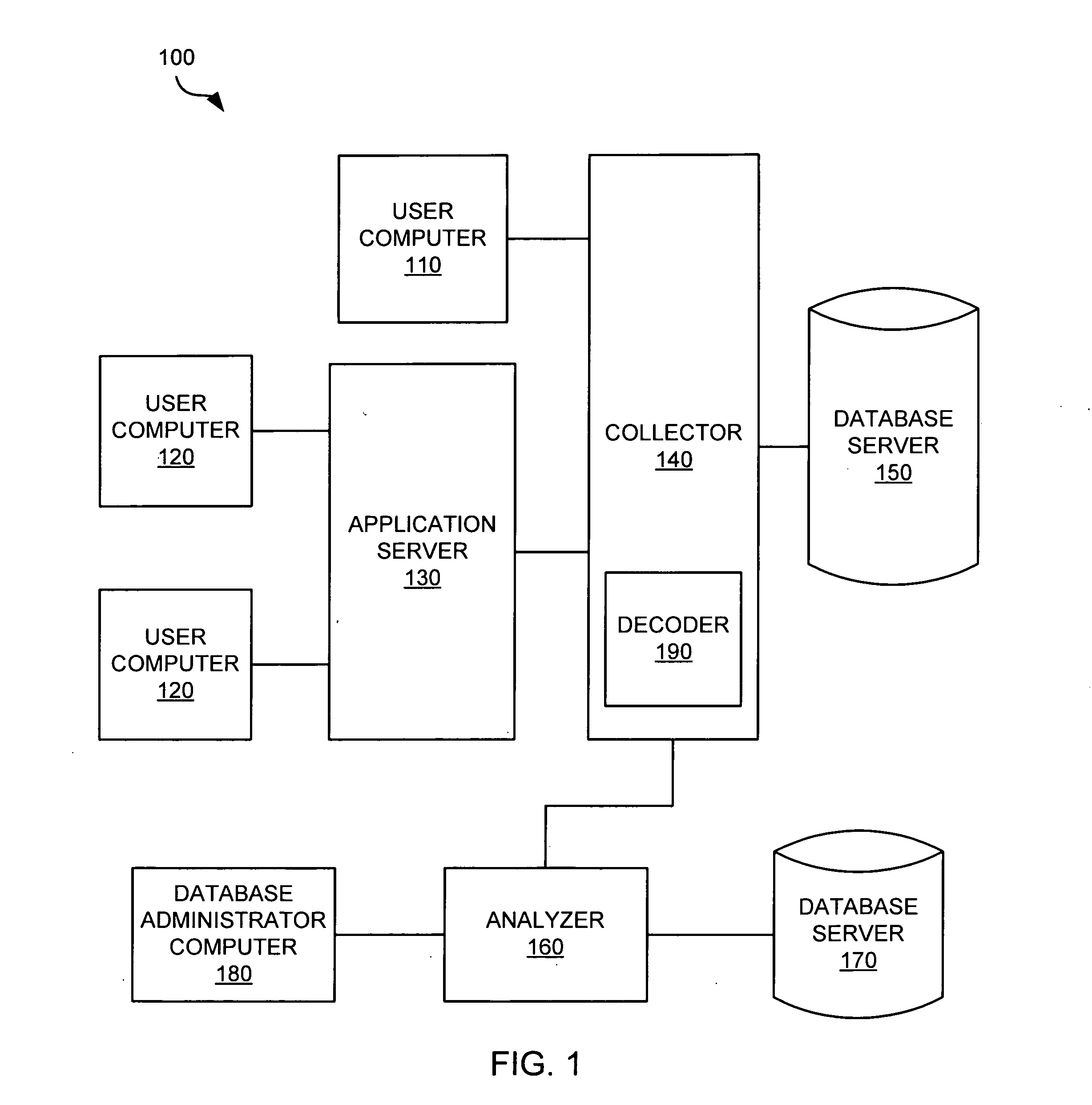
[0028]FIG. 1 is a block diagram of a system 100 for determining interactions of users with an application in an exemplary implementation of the invention. The system 100 includes a user computer 110, user computers 120, an application server 130, a collector 140, a database server 150, an analyzer 160, a database server 170, and a database administrator computer 180. The collector 140 includes a decoder 190.
[0029] The user computer 110 is linked to the collector 140. The user computers 120 are linked to the application server 130. One user computer 110 and two user computers 120 are shown for the sake of simplicity, although multiple user computers 110 and more than two user computers 120 may be included. The application server 130 is linked to the collector 140. Other embodiments may have multiple application servers 130 that are also linked to the collector 140. The collector 140 is linked to the database server 150 and the analyzer 160. The analyzer 160 is linked to the database...
PUM
 Abstract
Description
Claims
Application Information