

Multifunction server system
- Summary
- Abstract
- Description
- Claims
- Application Information
AI Technical Summary
Benefits of technology
Problems solved by technology
Method used
Image

Examples
Embodiment Construction
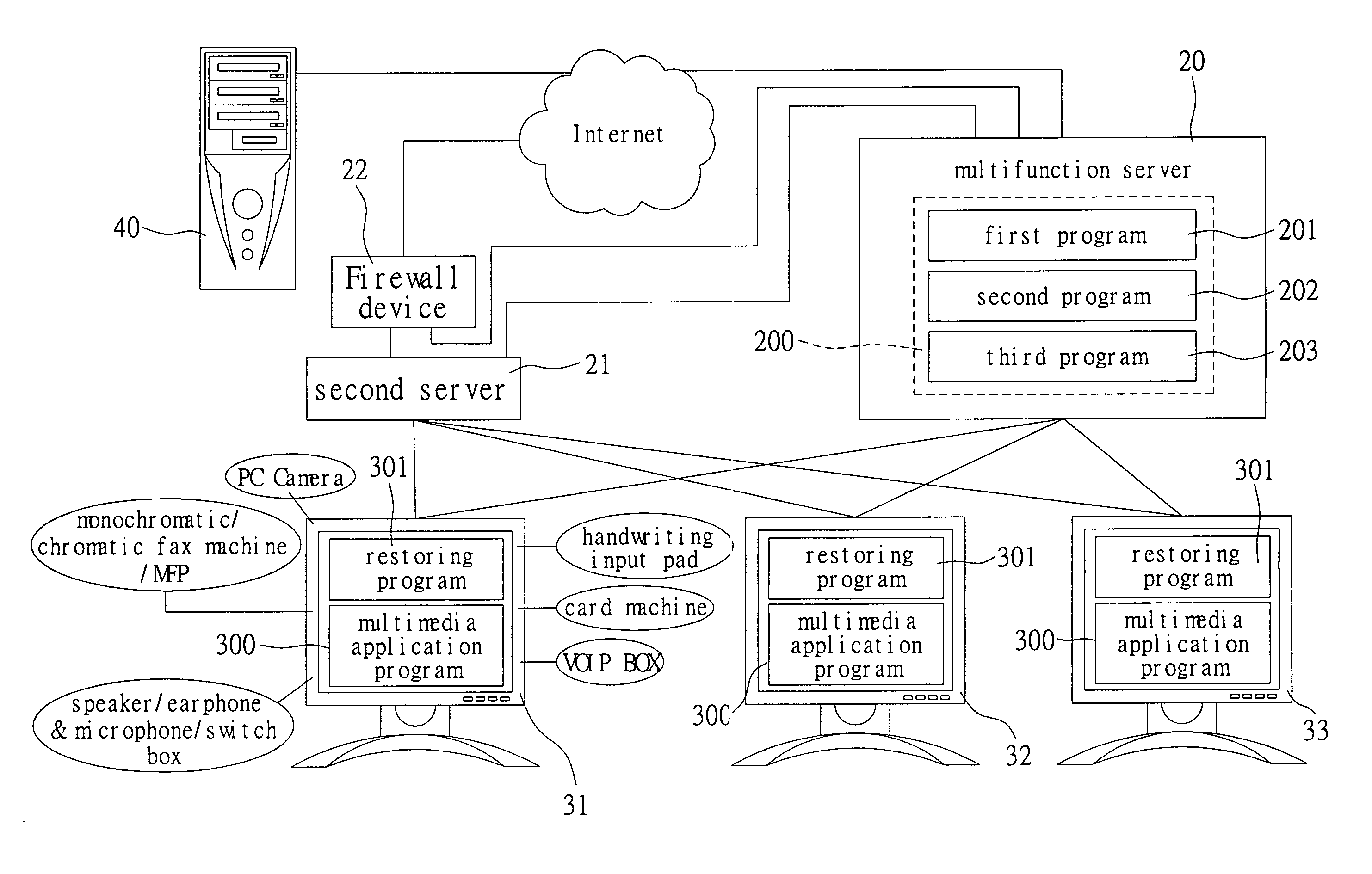
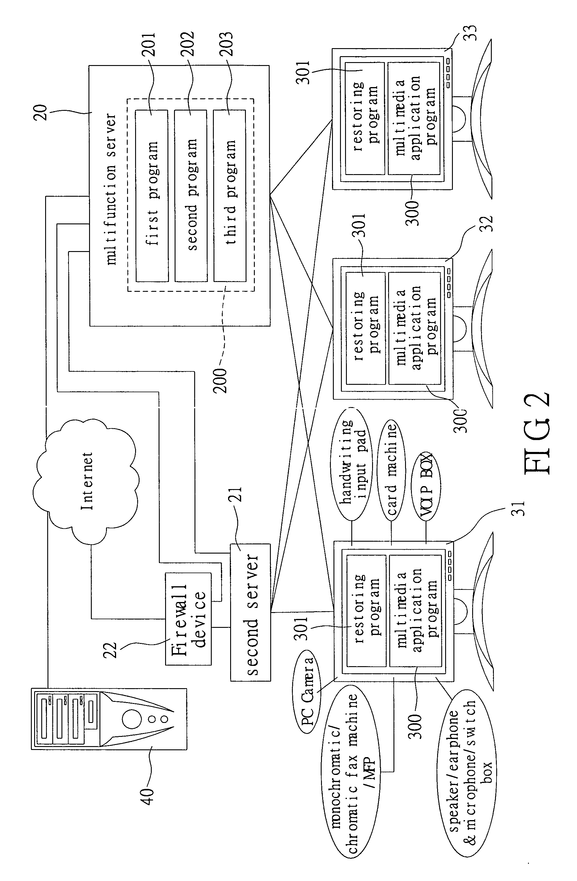
[0021] Reference is made to FIG. 2, which is a schematic diagram of a multifunction server system in accordance with the first embodiment of the present invention. The multifunction server system has a multifunction server 20, a second server 21, a Firewall device 22, such a Firewall computer system or a Firewall program, a first host 31, a second host 32 and a third host 33. The multifunction server 20 is connected to the Internet directly or via the Firewall device 22. The second server 21 is connected to the multifunction server 20 and connected to the Internet via the Firewall device 22. The first host 31, the second host 32, and the third host 33 are connected to both of the multifunction server 20 and the second server 21 via network interfaces. The multifunction server 20 is used to process multimedia messages, such as video mail, and the second server is used to process common e-mail.
[0022] The multifunction server 20 meets the multifunction requirements by executing softwa...
PUM
 Abstract
Description
Claims
Application Information