Container closure with biased closed tube valve

Active Publication Date: 2007-03-08
WESTROCK DISPENSING SYST
View PDF8 Cites 12 Cited by
  • Summary
  • Abstract
  • Description
  • Claims
  • Application Information

AI Technical Summary

Benefits of technology

[0007] The container closure of the invention has a simple construction that is comprised of two component parts, a closure base that includes a lid, and the valve element. Each of the component parts is constructed of a plastic, with the plastic of the valve element being more flexible and more resilient than the plastic of the closure base.
[0010] A lid is attached to the base by a living hinge. The hinge allows the lid to be moved between a closed position where the lid is positioned over the base exterior surface and over the spout and dispensing orifice, and an opened position where the lid is displaced from the base exterior surface and the dispensing orifice.
[0013] The resiliency and flexibility of the valve element allows the valve element to move between closed and opened positions relative to the base and the base dispensing orifice. The resiliency of the valve element biases the valve element to the closed position where the exterior surface of the valve element engages against the second portion of the base cylindrical wall and closes communication through the base cavity to the dispensing orifice. When the container closure is attached to a liquid container and the pressure of the liquid in the container is increased, for example by inverting the container and / or squeezing the container, the liquid flows through the retainer hole to the valve element exterior surface. The pressure of the liquid causes the valve element to flex away from the second portion of the base cylindrical wall and opens communication between the container attached to the container closure and the base dispensing orifice.

Problems solved by technology

Each of these basic types of prior art closures are disadvantaged in that they require some manual movement of the cap to close the container dispensing orifice.
This could result in the cap falling off of the container, or could result in an incomplete seal of the container dispensing orifice.
This also could result in the cap falling off of the container, or the cap not sealing the container dispensing orifice.
In both situations, the container dispensing orifice is left unsealed, which could result in the spoiling of the container contents or the drying out of the container contents.

Method used


Image

  • Container closure with biased closed tube valve
  • Container closure with biased closed tube valve
  • Container closure with biased closed tube valve

Examples


Embodiment Construction

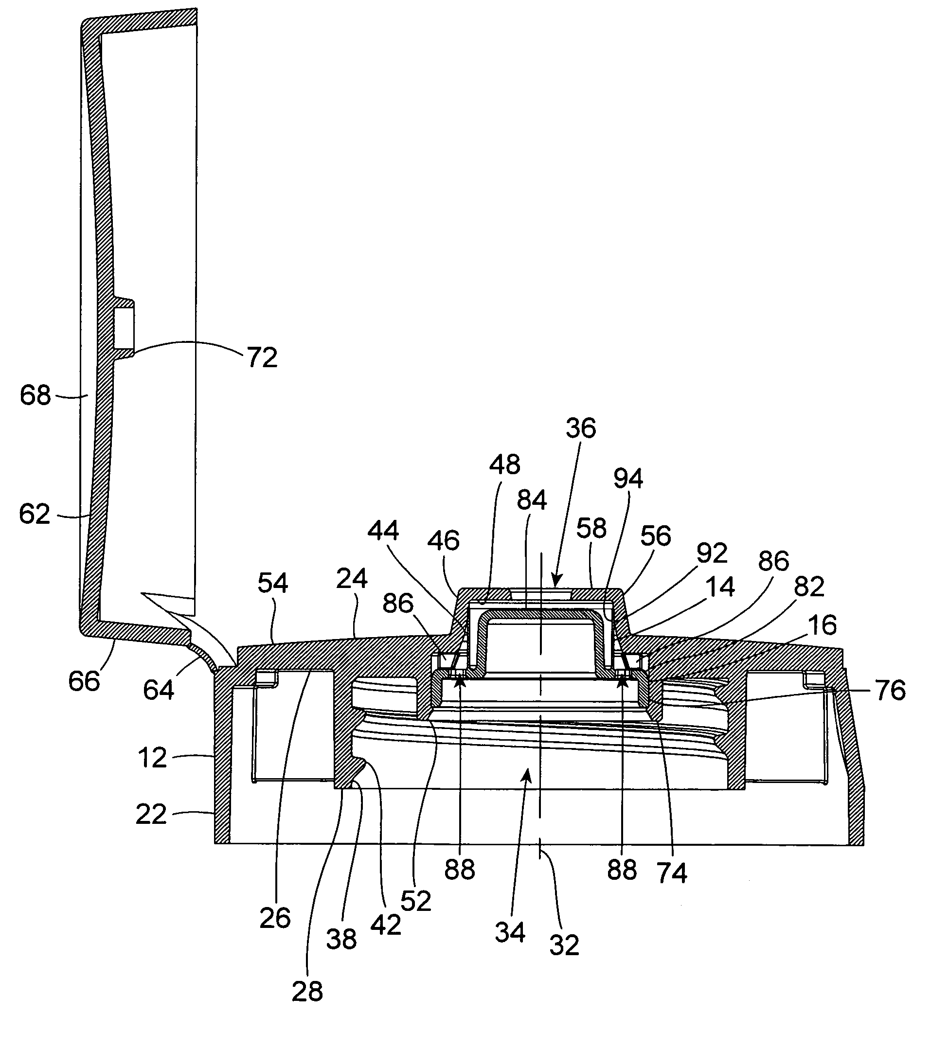
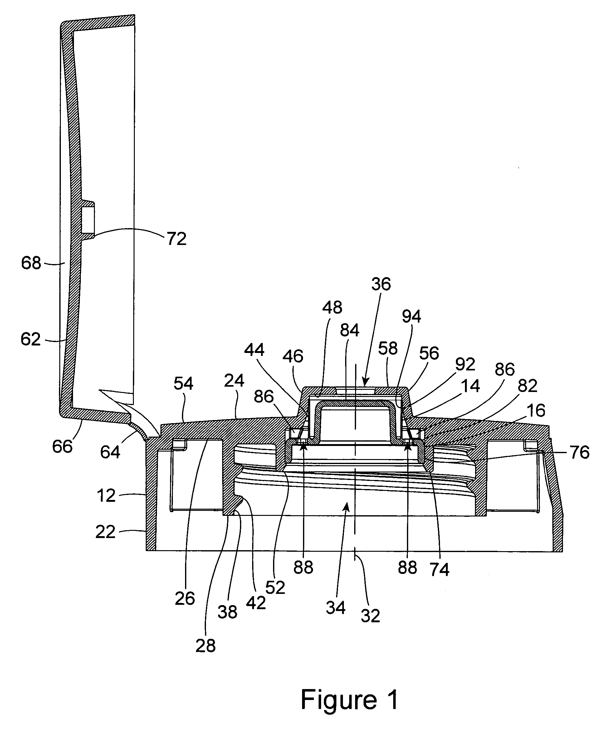
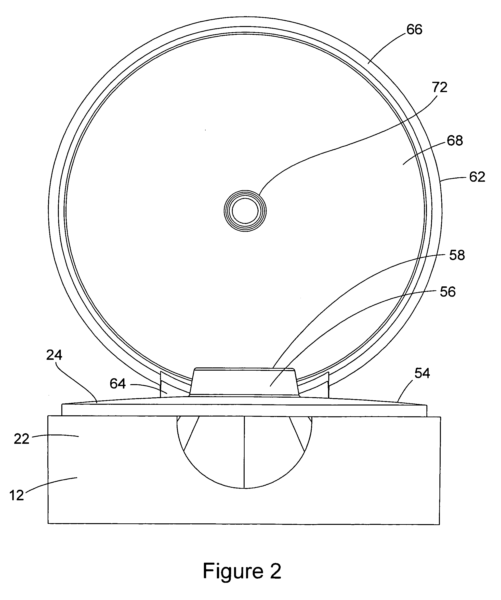
[0019] The container closure of the invention has a simplified, inexpensive construction that is comprised of only two component parts. The closure is designed to be removably attachable to a container by being screw threaded on a threaded neck of the container that surrounds the dispensing opening of the container. Alternatively, the closure could be snap fit to the container over the container dispenser opening, or be attached to the container by some other method, for example by a bayonet fitment. Although a screw threaded connector will be described on the container closure, the container closure should not be interpreted as being limited to this particular type of connector.

[0020] As stated earlier, in the preferred embodiment of the invention, each of the component parts of the container closure is constructed of a plastic material. The two basic component parts of the container closure include a closure base 12, and a valve element 14 having an integral valve retainer 16. Th...


PUM


Abstract

A closure is removably attachable to a container and comprises a dispensing orifice and a tubular valve element that is biased closed blocking communication of the container with the orifice. By inverting the container so that a liquid contents of the container exerts pressure on the valve element, or by squeezing the container causing the liquid contents to exert pressure on the valve element, the valve element opens communication with the dispensing orifice allowing the liquid contents to be dispensed from the container. On removing the pressure from the valve element, the valve element resiliently closes the dispensing orifice.

Description

BACKGROUND OF THE INVENTION [0001] (1) Field of the Invention [0002] The present invention pertains to a closure for a container that is inverted and / or manually squeezed to dispense the contents of the container through an orifice of the closure. Specifically, the present invention pertains to a closure that is removably attachable to the container and comprises a dispensing orifice and a tubular valve element that is biased closed to block communication of the container with the dispensing orifice. By inverting the container so that a liquid contents of the container exerts pressure on the exterior surface of the valve element, or by squeezing the container causing the liquid contents to exert pressure on the exterior surface of the valve element, the valve element opens and allows the liquid contents to be dispensed from the container. On removing the pressure from the valve element, the valve element resiliently closes and again blocks the dispensing orifice. [0003] (2) Descript...

Claims


Application Information

Patent Timeline
IPC IPC(8): B65D35/38B65D47/00
CPCB65D47/2018
Inventor FOSTER, DONALD D.LAFFEY, MARTIN S.
Owner WESTROCK DISPENSING SYST
Why Eureka
Try Eureka