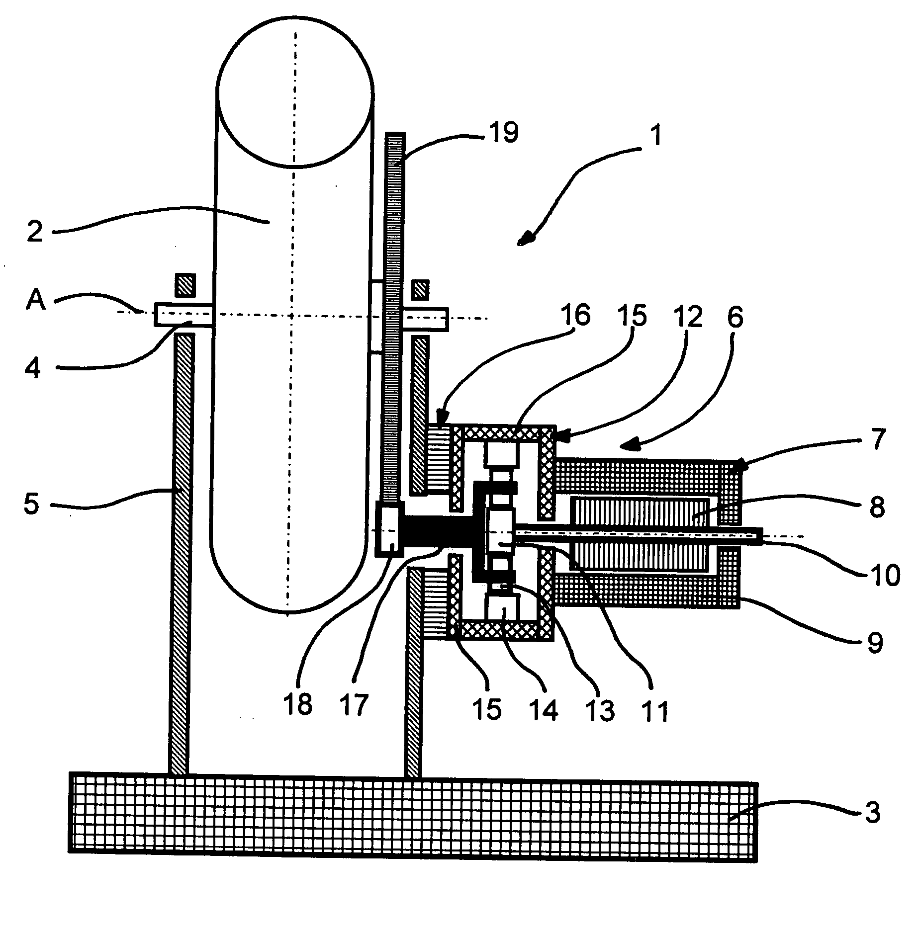
Adjustment and stabilization unit with a force-sensing device for torque measurement

Active Publication Date: 2007-03-29
MOOG GMBH
View PDF11 Cites 17 Cited by
  • Summary
  • Abstract
  • Description
  • Claims
  • Application Information

AI Technical Summary

Benefits of technology

[0016] The decoupling of the force-sensing device from the adjustment drive prevents exertion of a load on the adjustment drive and its components, as essential portions of the exerted torque and possible bending stresses are transmitted to the force-sensing device. The arrangement of the force-sensing device furthermore permits the use of an adjustment drive designed solely for the requirements of the adjustment and stabilization unit. Apart from rotary drives, linear drives may also be employed. The employment of the force-sensing device furthermore permits matching of the applied torque and a corresponding measuring signal, so that exact control of the drive is possible with a response characteristic matching that of the stabilization control circuit. While the positioning of the force-sensing device between the drive mounting and the adjustment drive produces a certain deviation between the actual measured quantity and the ideal measured quantity (i.e., of the torque exerted on the rotational mass by the moving platform when the rotor is not yet accelerated), by the tailored selection of the adjustment drive, these deviations can be kept so small that a clear improvement of the stabilizing quality is still achieved.
[0018] In a preferred embodiment, the adjustment drive comprises an electric motor and at least one single-stage gear, permitting a simple and effective drive for adjusting position of the rotational mass. Depending on the requirements of the adjustment and stabilization unit, the gear can be designed either as a single-stage cylindrical gear for transmitting rotational motion of the electric motor to the rotational mass as evenly as possible, or as a planetary gear train to cause the rotational motion of the rotor, or the acceleration of the rotational mass on the gear, to be direct as possible.
[0019] Another embodiment provides that the driving device of the adjustment drive is arranged adjacent the single-stage gear so that the force-sensing device measures the torque arising between the platform and the gear case. This arrangement permits a simple and effective measurement of torque. By the selection of a high gear ratio, the deviation of the measured torque from the actual torque can be kept low, and a particularly good stabilization quality can be achieved.
[0025] For a simple and secure connection of the force-sensing device with the drive mounting and the adjustment drive, the rings can be designed as flanges. Here, the webs are designed as points of measurable elongation for a simple measurement of the elongation.
[0026] A preferred embodiment provides that the two rings which can be rotated in opposite directions and / or that the elastically-deformable webs can be made of aluminum. The manufacture of the rings of aluminum permits a good strength for an attachment at the drive mounting and the adjustment drive, while permitting the required elasticity for measuring an elongation.
[0028] The stabilization control circuit for controlling the adjustment drive can convert the signals of a gyroscope of another rotational mass, or the position signal of another rotational mass already stabilized by a gyroscope and / or externally-set adjustment signals, into control signals for controlling the rotation of the mass. The stabilization control circuit may permit control of the adjustment drive with respect to other manipulated variables or movements of the adjustment and stabilization unit, and thus may facilitate the control of the adjustment drive by means of torque measurement.

Problems solved by technology

Each error between these two coordinated motions results in a corresponding error in the stabilization angle.
These adjustment drives are only suitable for rotational masses with a small out-of-balance moments, as the holding torque exerted by the drive motor to counter an out-of-balance moment becomes larger as the mass and / or gear ratio becomes larger.
Due to the increase in the unbalance of the mass, the sensitivity to disturbances in the vertical direction has also increased, with a resulting negative influence on stabilization quality.
However, the practicality of using an auxiliary gyroscope is limited, as the reaction time between generation of the anticipatory signal from the auxiliary gyroscope and the response of the driven rotational mass is too short.
In weapon systems with larger elevation adjustment angles of up to about 90° (e.g., for the use on armored vehicles used for air defense), such linear control drives have considerable disadvantages as the gear ratio of the rotational motion of the motor into the slewing motion of the weapon system into the elevation direction effectively increases with the increase of the adjustment angle, making it difficult to compensate for as to its control and drive.
Such an arrangement would require measuring the torque of moving parts, leading to additional complexity for transmitting the measuring signals (e.g., by means of slip rings, trailing cables, radio, etc.) from the rotating part of the drive to the static part of the stabilization unit.
However, the torque exerted by the rotational mass is not transmitted to the stator of the motor, as the acceleration moments are supported at the still-stationary mass of the rotor.

Method used


Image

  • Adjustment and stabilization unit with a force-sensing device for torque measurement
  • Adjustment and stabilization unit with a force-sensing device for torque measurement
  • Adjustment and stabilization unit with a force-sensing device for torque measurement

Examples


Embodiment Construction

[0036] At the outset, it should be clearly understood that like reference numerals are intended to identify the same structural elements, portions or surfaces consistently throughout the several drawing figures, as such elements, portions or surfaces may be further described or explained by the entire written specification, of which this detailed description is an integral part. Unless otherwise indicated, the drawings are intended to be read (e.g., cross-hatching, arrangement of parts, proportion, degree, etc.) together with the specification, and are to be considered a portion of the entire written description of this invention. As used in the following description, the terms “horizontal”, “vertical”, “left”, “right”, “up” and “down”, as well as adjectival and adverbial derivatives thereof (e.g., “horizontally”, “rightwardly”, “upwardly”, etc.), simply refer to the orientation of the illustrated structure as the particular drawing figure faces the reader. Similarly, the terms “inw...


PUM


Abstract

An adjustment and stabilization unit (1), such as for a weapon, includes a movable platform (3), a rotational mass (2) mounted on the platform and stabilized in inertial space, and an adjustment drive (6) for adjusting the rotational mass. The adjustment drive includes a driving device (7) connecting the adjustment drive with the rotational mass, a force-sensing device (16) for measuring torque, and at least one stabilization control circuit for controlling the rotary adjustment drive by means of the measured torque. The force-sensing device (16) has an annular design and is arranged between the platform (3) and the adjustment drive (6). The driving device has a shaft (10) that extends through force-sensing device (16). The force-sensing device measures the torque transmitted between the adjustment drive and the platform, and being transmitted to the adjustment drive as a result of an acceleration of the rotational mass.

Description

TECHNICAL FIELD [0001] The present invention relates to an adjustment and stabilization unit, such as for adjusting and stabilizing a weapon. The unit includes a movable platform, a rotational mass movably mounted on the platform and stabilized in inertial space, and an adjustment drive for adjusting the position of the rotational mass relative to the platform. The adjustment drive includes a driving device, a force-sensing device for measuring torque, and a stabilization control circuit for controlling the adjustment drive as a function of the measured torque. BACKGROUND ART [0002] The stabilization of the position of a rotational mass in inertial space on a moving platform (e.g., a rotary weapon unit mounted on a vehicle) is usually not achieved by controlling the rotational speed of the mass relative to the platform, but by controlling the rotational speed or the position of the rotational mass in inertial space by means of a gyroscope. The output signal of the gyroscope is suppl...

Claims


Application Information

Patent Timeline
IPC IPC(8): F41G5/06
CPCF41A27/30Y10T74/12F41G5/24F41G5/16F41G5/00F41G5/14
InventorSTEHLIN, BERNDEISELE, PETER
OwnerMOOG GMBH