Optical connector and fiber distribution unit

a technology of optical connectors and fiber distribution units, applied in the field of optical connectors, can solve the problems of incompatibility of hybrid splice connectors with standard connector formats, process can be awkward and time-consuming in the field, and commercially available optical connectors are not well suited for field installations

Active Publication Date: 2007-05-10
CORNING RES & DEV CORP
View PDF39 Cites 68 Cited by
  • Summary
  • Abstract
  • Description
  • Claims
  • Application Information

AI Technical Summary

Benefits of technology

[0018] According to another aspect of the present invention, a method for terminating an optical fiber in an optical connector also includes crimping fiber cable strength members to an adapter ring fitted to the backbone of the connector to provide axial strain relief.

Problems solved by technology

However, commercially available optical connectors are not well suited for field installations.
This process can be awkward and time consuming to perform in the field.
However, these hybrid splice connectors are not compatible with standard connector formats and require significant piecewise assembly of the connector in the field.
The handling and orientation of multiple small pieces of the connector can result in incorrect connector assembly that may either result in decreased performance or increase the chance of damaging the fiber.

Method used


Image

  • Optical connector and fiber distribution unit
  • Optical connector and fiber distribution unit
  • Optical connector and fiber distribution unit

Examples


Embodiment Construction

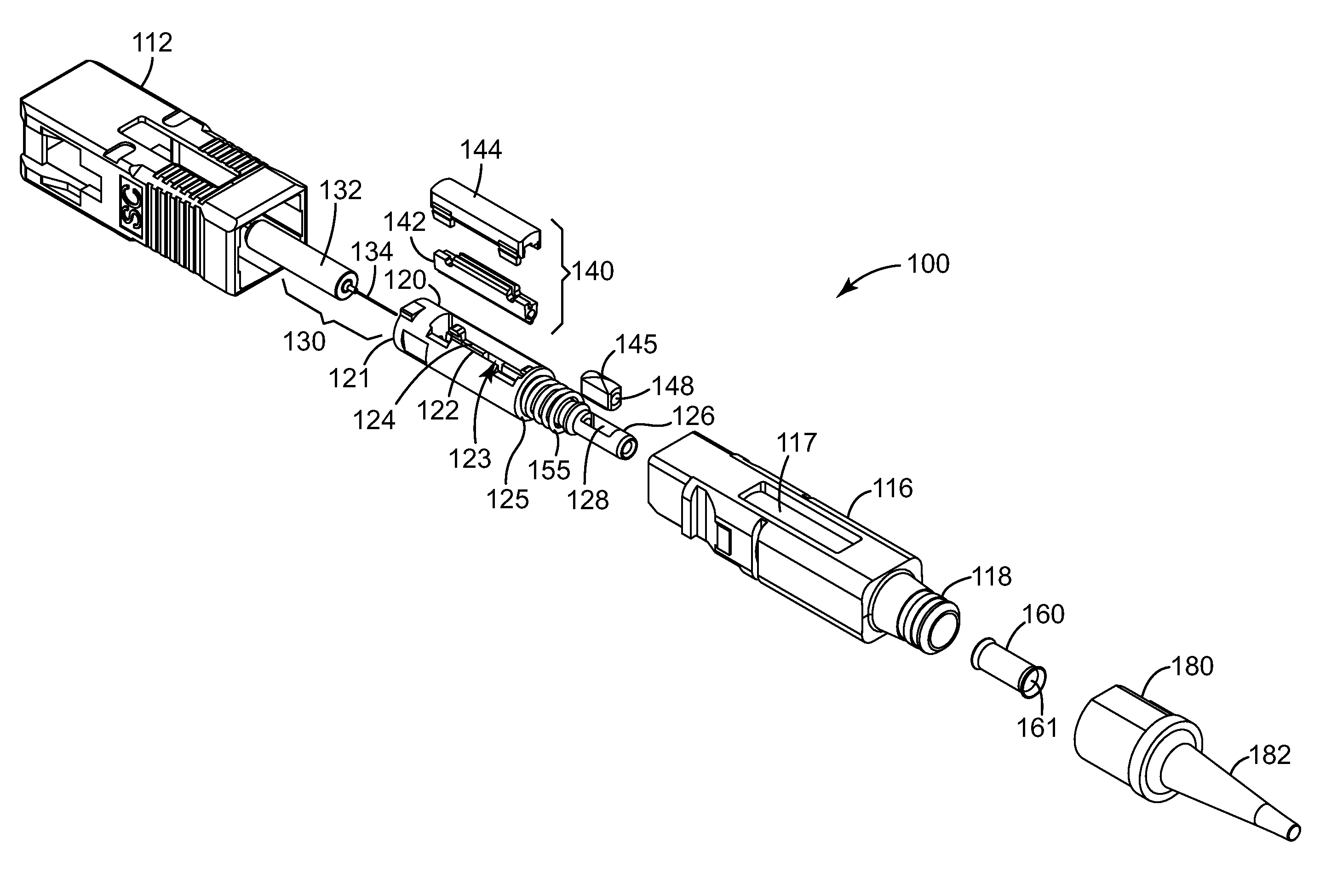
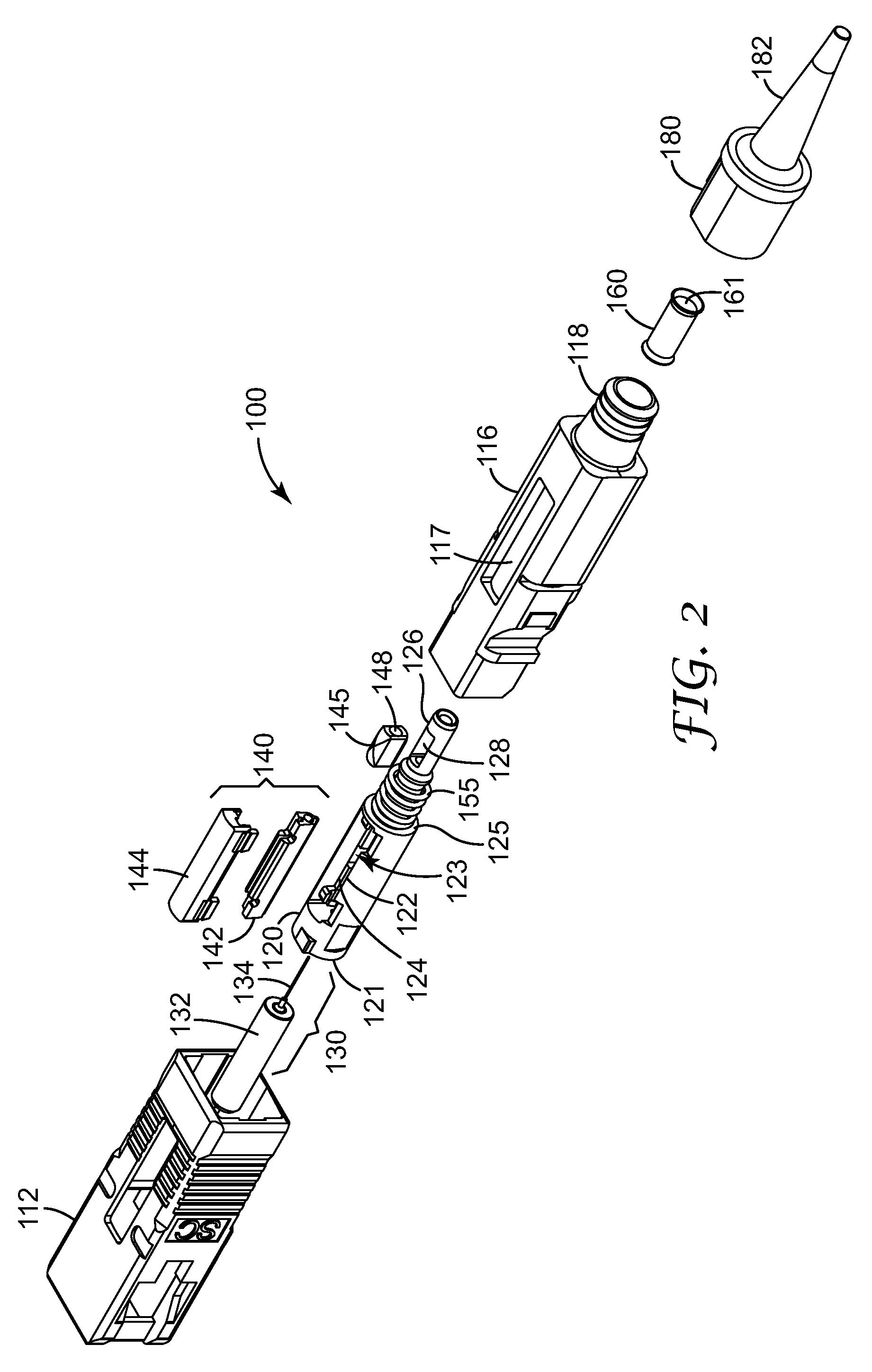
[0054] The present invention is directed to an optical connector. In particular, the optical connector of the exemplary embodiments is of compact length and is capable of straightforward field termination. Further, with the straightforward connector termination platform and procedure described herein, reduced assembly times in field termination applications can be accomplished. The exemplary connector(s) described herein can be readily installed and utilized for Fiber To The Home (FTTH) and / or Fiber To The X (FTTX) network installations. The exemplary connector(s) can be utilized in installation environments that require ease of use when handling multiple connections, especially where labor costs are more expensive.

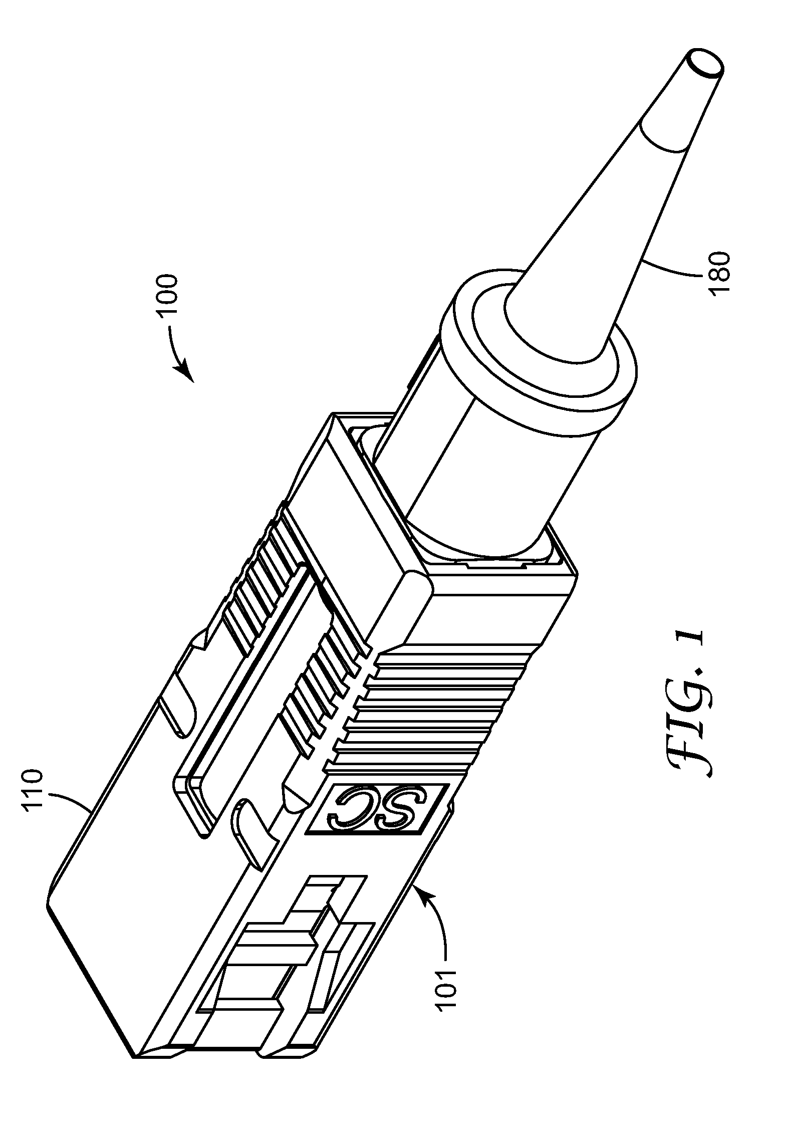
[0055] According to an exemplary embodiment of the present invention, an optical fiber connector 100 is shown in isometric view in FIG. 1 and in exploded view in FIG. 2. Optical connector 100 is configured to mate with a receptacle. For example, as shown in FIG. 1, exemp...


PUM


Abstract

An optical connector for terminating an optical fiber comprises a housing configured to mate with a receptacle and a collar body disposed in the housing. The collar body includes a fiber stub disposed in a first portion of the collar body, the fiber stub including a first optical fiber mounted in a ferrule and having a first end proximate to an end face of the ferrule and a second end. The collar body also includes a mechanical splice disposed in a second portion of the collar body, the mechanical splice configured to splice the second end of the fiber stub to a second optical fiber. The collar body also includes a buffer clamp configured within a third portion of the collar body, the buffer clamp configured to clamp at least a portion of a buffer cladding of the second fiber upon actuation. A fiber distribution unit is also provided.

Description

CROSS REFERENCE TO RELATED APPLICATIONS [0001] The present application claims the benefit of U.S. Provisional Application Ser. No. 60 / 729,629 filed on Oct. 24, 2005; U.S. Provisional Application Ser. No. 60 / 743,119 filed on Jan. 11, 2006; U.S. Provisional Application Ser. No. 60 / 744,180 filed on Apr. 3, 2006; U.S. Provisional Application Ser. No. 60 / 805,038 filed on Jun. 16, 2006; and U.S. Provisional Application Ser. No. 60 / 819,226 filed on Jul. 7, 2006. The disclosures of each of the aforementioned Provisional Applications are incorporated by reference herein in their entirety.BACKGROUND OF THE INVENTION [0002] 1. Field of the Invention [0003] The present invention is directed to an optical connector. [0004] 2. Related Art [0005] Mechanical optical fiber connectors for the telecommunications industry are known. For example, LC, ST, FC, and SC optical connectors are widely used. [0006] However, commercially available optical connectors are not well suited for field installations. T...

Claims


Application Information

Patent Timeline
Patent Type & Authority Applications(United States)
IPC IPC(8): G02B6/36
CPCG02B6/3801G02B6/3802G02B6/3806G02B6/3846G02B6/245G02B6/25G02B6/38875G02B6/38
Inventor LARSON, DONALD K.WINBERG, PAUL N.RAIDER, WESLEY A.PARK, CHANSOOLMAK, WAI-FUNGCARPENTER, JAMES B.GLATZL, FRANK J.
Owner CORNING RES & DEV CORP
Why Eureka
Try Eureka