Controlled tissue dissection systems and methods

a tissue dissection and control technology, applied in the field of expandable tissue dissection devices, can solve the problems of ineffective tactile sense of the patient, inadvertent tissue injury, and treatment procedure carries some degree of risk of injury to healthy tissues, and achieve the effect of restricting the lateral motion of the implan

Active Publication Date: 2019-08-08
BIOPROTECT
View PDF3 Cites 2 Cited by
  • Summary
  • Abstract
  • Description
  • Claims
  • Application Information

AI Technical Summary

Benefits of technology

The patent describes an implant that can be expanded to dissect tissue. The implant has a restrictor that can prevent the implant from expanding laterally or vertically, and can also restrict expansion in the direction of the first surface. The restrictor can be an inelastic pliable strip or a through hole periphery line that firmly attaches two parallel surfaces of the implant. This invention helps to control the expansion of the implant and ensures accurate tissue dissection.

Problems solved by technology

One of the most challenging phases of the operation is a dissection and / or separation of the prostate from the rectal wall, where in laparoscopy or robotic surgery the practitioner's tactile sense is not effective.
In any case, the treatment procedure carries some degree of risk of injury to healthy tissues.
For example, during surgery, use of surgical instruments in small, tight spaces can lead to inadvertent tissue injury.
Radiation therapy or localized release of chemical substances can result in an intensity gradient between treated tissue and healthy tissue, and radiation or chemical injury to healthy tissues.
As a result, a total energy or chemical dose for local treatment which should be applied to a tissue is limited by a dose which may be transmitted to healthy adjacent tissues.
Moreover, some tissues and organs are more sensitive to radiation and chemical damage than others, and thus treatment of tissue adjacent to such tissues and organs can be severely limited.

Method used


Image

  • Controlled tissue dissection systems and methods
  • Controlled tissue dissection systems and methods
  • Controlled tissue dissection systems and methods

Examples


example expandable

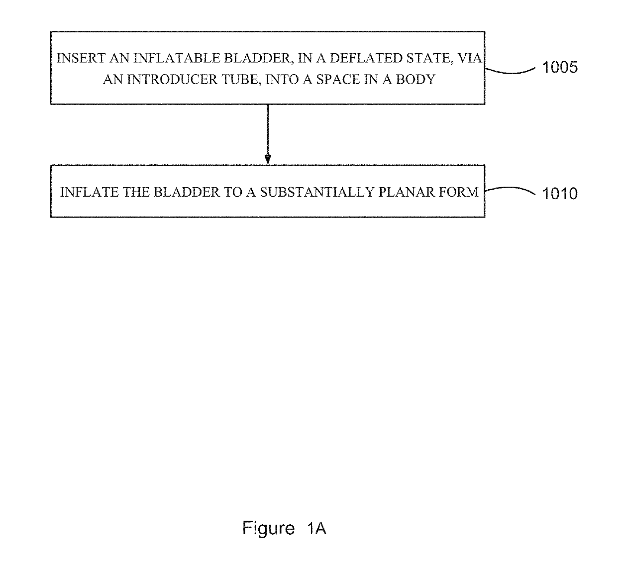
Devices for Tissue Dissection / Separation

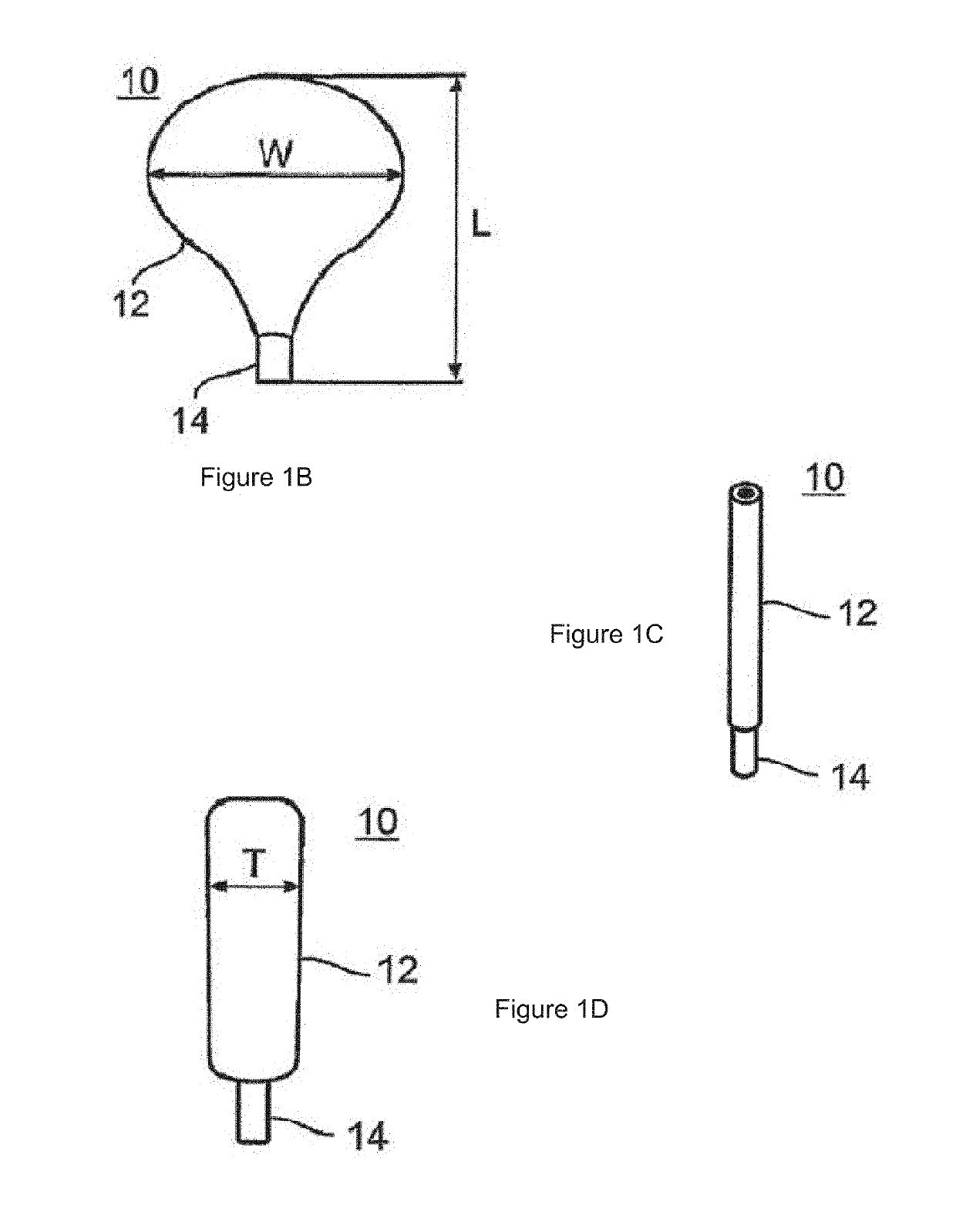
[0217]Reference is now made to FIGS. 1B-D, which are simplified illustrations of an inflatable bladder constructed according to an example embodiment of the present invention.

[0218]FIGS. 1B-1D illustrate an inflatable bladder which is referred to herein as device 10.

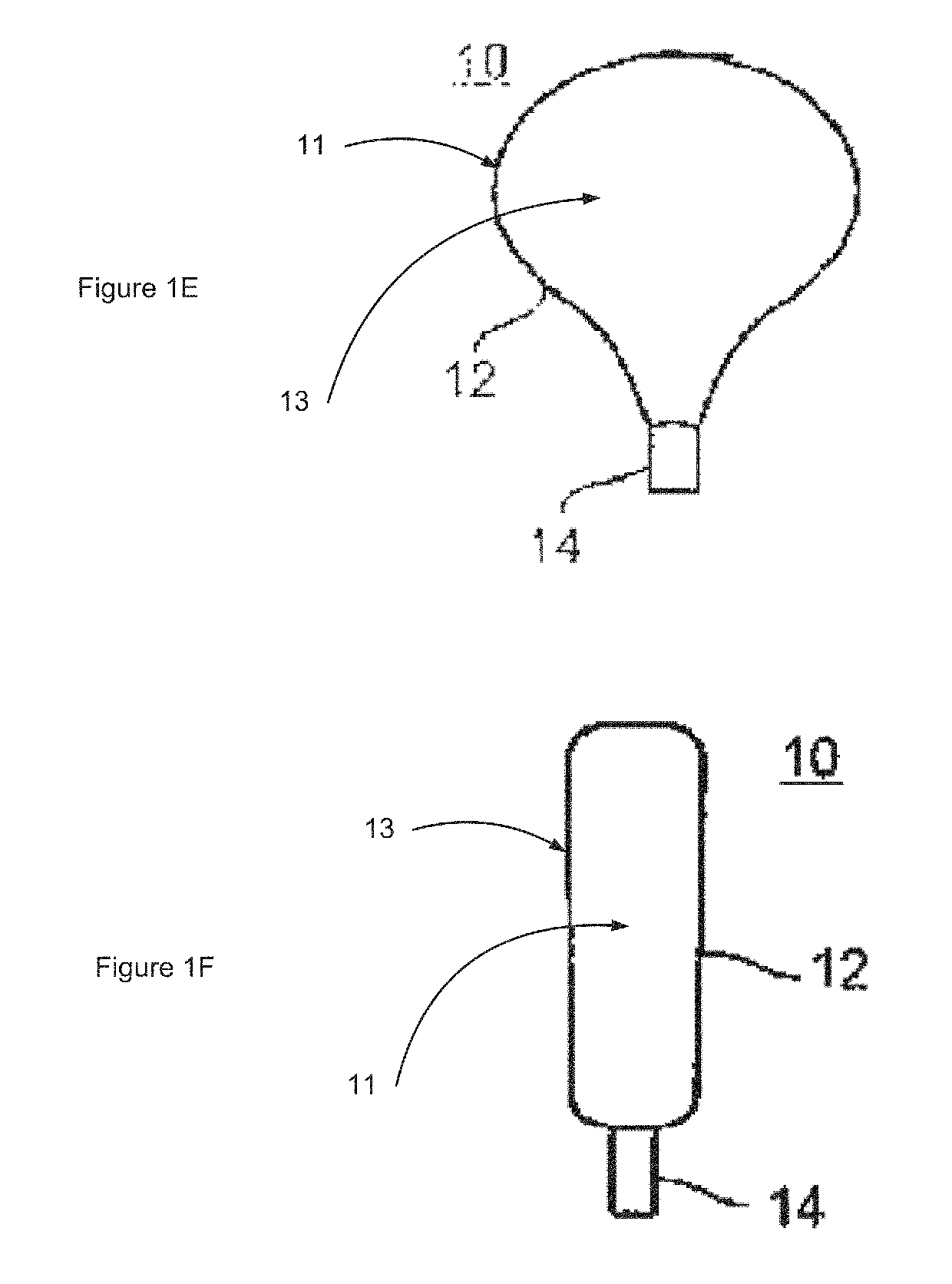
[0219]Device 10 includes a bladder 12 which can be constructed out of a biocompatible material. As used herein the term bladder refers to a chamber having an inner volume when expanded and less inner volume when collapsed.

[0220]Although FIGS. 1B-1D illustrate a planar balloon shape having an expanded state of length L (FIG. 1B e.g. from 1 to 20 cm), an expanded state of width W (FIG. 1B e.g. from 1 to 20 cm) and an expanded state of thickness T (FIG. 1D e.g. from 1 to 10 cm), it will be appreciated that bladder 12 can be fabricated in any shape suitable for uniform tissue lateral dissection and / or vertical displacement thus minimizing any localized pressure on the tissue.

[0221]In s...


PUM


Abstract

A tissue dissecting device, including an inflatable bladder configured to be inserted into a body via an introducer tube in a compact deflated state, and to be inflated to a substantially planar form in a manner which dissects tissue. A method for dissecting tissue, including inserting an inflatable bladder, in a deflated state, via an introducer tube, into a space in a body, and inflating the bladder to a substantially planar form, thereby dissecting tissue. A method for dissecting tissue, including inserting an introducer tube via an incision into a body, inserting an inflatable bladder, in a deflated state, via the introducer tube, into a space in the body, pulling the introducer tube back at least a length of the deflated bladder, inflating the bladder, via a filling tube, to a substantially planar form, thereby dissecting tissue, disconnecting the filling tube from the bladder, retracting the filling tube and the introducer tube from the body. Related apparatus and methods are also described.

Description

RELATED APPLICATIONS[0001]The present application is a continuation of U.S. patent application Ser. No. 13 / 521,080 having a 371 date of Jul. 9, 2012 which is incorporated herein by reference. U.S. patent application Ser. No. 13 / 521,080 is a 371 national stage entry of PCT / IL2011 / 000018 filed on Jan. 6, 2011 which is incorporated herein by reference. PCT / IL2011 / 000018 claims benefit under 119(e) of U.S. provisional patent application 61 / 292,899, filed on Jan. 7, 2010, and of U.S. provisional patent application 61 / 412,490, filed on Nov. 11, 2010, with same inventor. The disclosures of the above-mentioned applications are incorporated herein by reference.FIELD AND BACKGROUND OF THE INVENTION[0002]The present invention, in some embodiments thereof, relates to expandable tissue dissecting devices, and, more particularly but not exclusively, to directionally controllable inflatable, optionally implantable, bladders configured for tissue dissection.[0003]Dissecting and / or separating tissue...

Claims


Application Information

Patent Timeline
Patent Type & Authority Applications(United States)
IPC IPC(8): A61B8/12A61B17/32A61B8/00
CPCA61B8/12A61B17/320016A61B8/445A61B2034/107A61B2017/320048
Inventor SHOHAT, SHAUL
Owner BIOPROTECT
Why Eureka
Try Eureka