Keyboard device for keyboard instrument

a keyboard and keyboard technology, applied in the field of keyboard devices for keyboard instruments, can solve the problems of increasing manufacturing costs, increasing manufacturing steps, and difficult disassembly of chassis parts, and achieve the effects of reducing manufacturing costs, preventing noise generation, and limiting lateral motion of hammers

Active Publication Date: 2007-04-24
KAWAI MUSICAL INSTR MFG CO
View PDF9 Cites 24 Cited by
  • Summary
  • Abstract
  • Description
  • Claims
  • Application Information

AI Technical Summary

Benefits of technology

[0011]It is a first object of the present invention to provide a keyboard device for a keyboard instrument, which is capable of ensuring sufficient strength of boundary portions of chassis and preventing generation of noise, while restricting lateral motion of hammers.
[0012]It is a second object of the present invention to provide a keyboard device for a keyboard instrument, which is capable of sufficiently reinforcing the rigidity of chassis in the front-rear direction while restricting lateral motion of hammers, without increasing the size of the keyboard device.

Problems solved by technology

To eliminate this inconvenience, if the intermediate chassis 81a and 81a are bonded to each other, this increases the number of manufacturing steps, which increases the manufacturing costs, and makes it difficult to disassemble the chassis assembly 81.
To solve this problem, it can be considered that the ribs 92 or other reinforcing members are provided at locations other than the locations below the sidewalls 90 so as to reinforce the chassis assembly 81, but in this case, there is a problem of the keyboard device being inevitably increased in size.

Method used


Image

  • Keyboard device for keyboard instrument
  • Keyboard device for keyboard instrument
  • Keyboard device for keyboard instrument

Examples


first embodiment

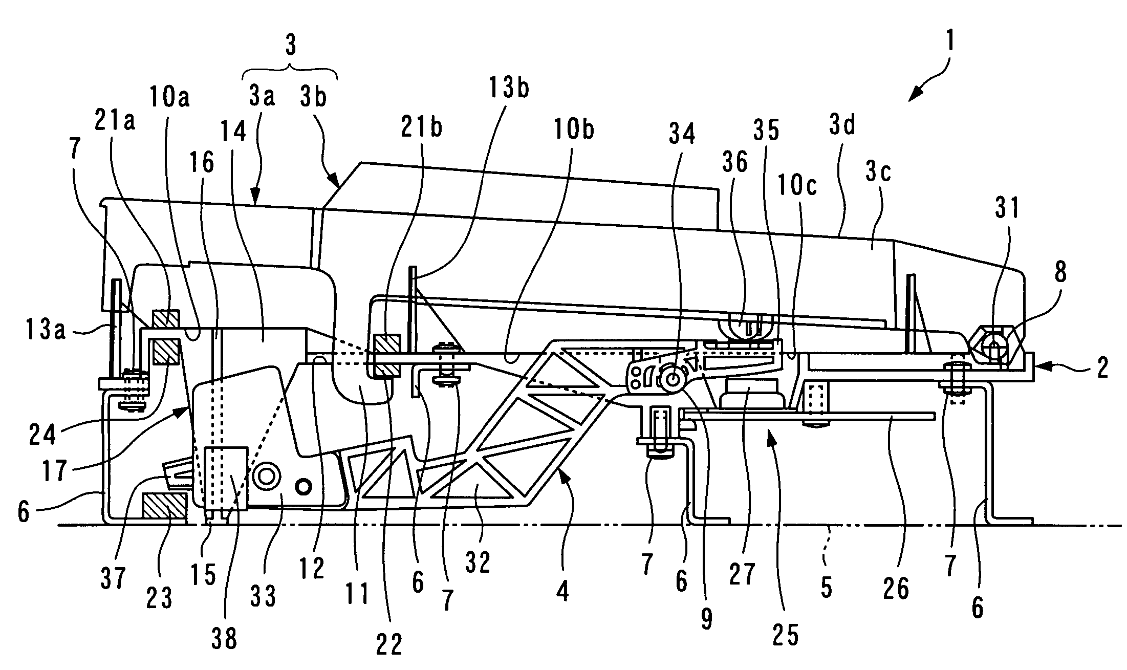
[0066]FIGS. 1 and 2 show a keyboard device for an electronic piano, according to the present invention. The keyboard device 1 is for use in an 88-key piano, and includes a chassis assembly 2, 88 keys 3 comprised of white keys 3a (only one which is shown) and black keys 3b (only one which is shown) pivotally mounted on the rear end of the chassis assembly 2, and hammers 4 pivotally mounted to the central portion of the chassis assembly 2.

[0067]The chassis assembly 2 is constituted by a total of eight chassis: seven basic chassis 2a (one of which is shown in FIG. 3, and two of which are shown in FIG. 5), and a chassis 2b (see FIG. 4) for the highest pitch range, and the eight chassis are supported on a keybed 5 in a state arranged side by side in the left-right direction.

[0068]As shown in FIG. 3A, each basic chassis 2a is formed with rows of supports and holes, referred to hereinafter, for supporting the keys 3 and the hammers 4. The rows of supports and holes are provided for the res...

second embodiment

[0084]Next, a keyboard device for a keyboard instrument, according to the present invention will be described in detail with reference to FIGS. 7 to 14.

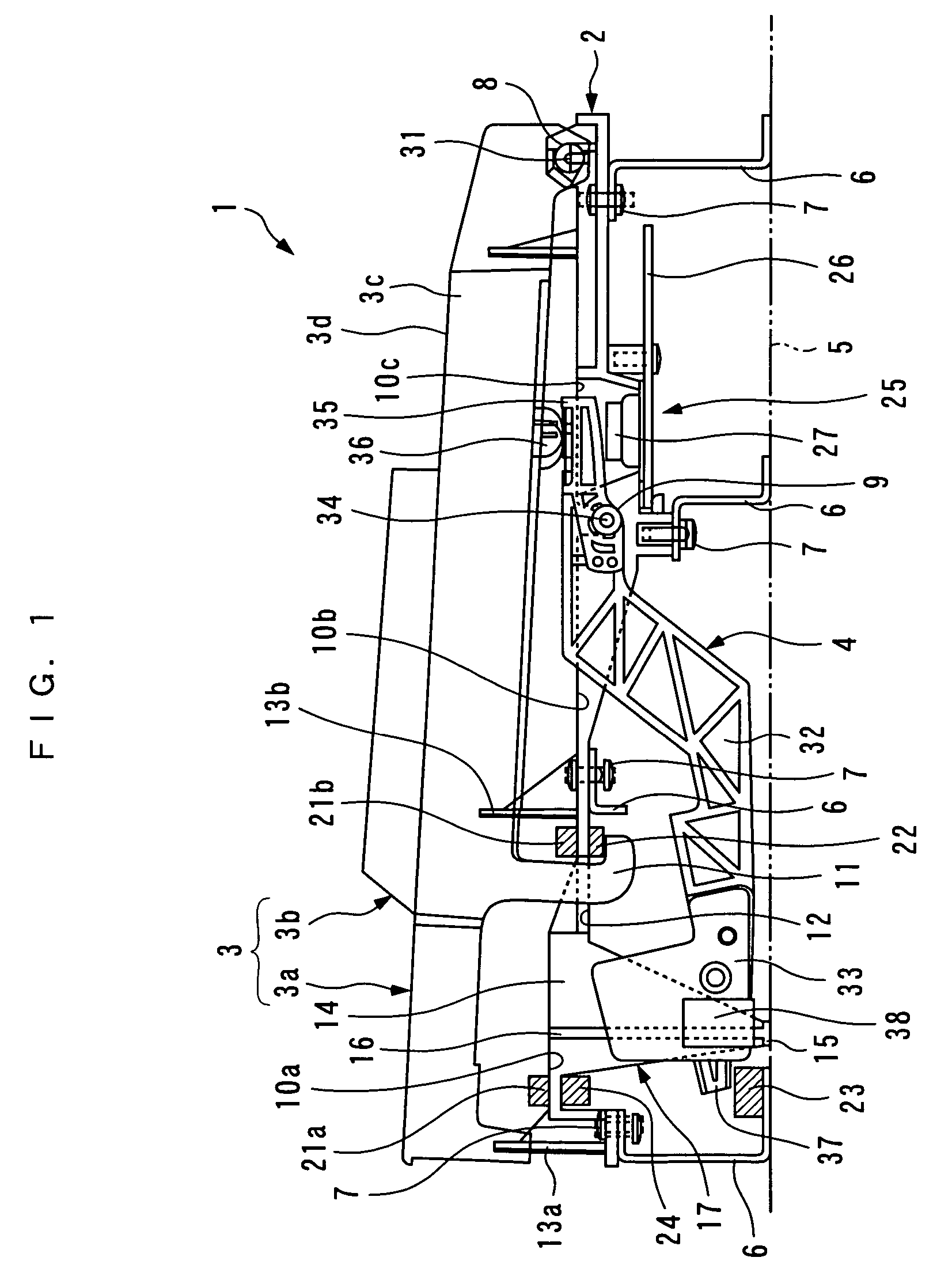
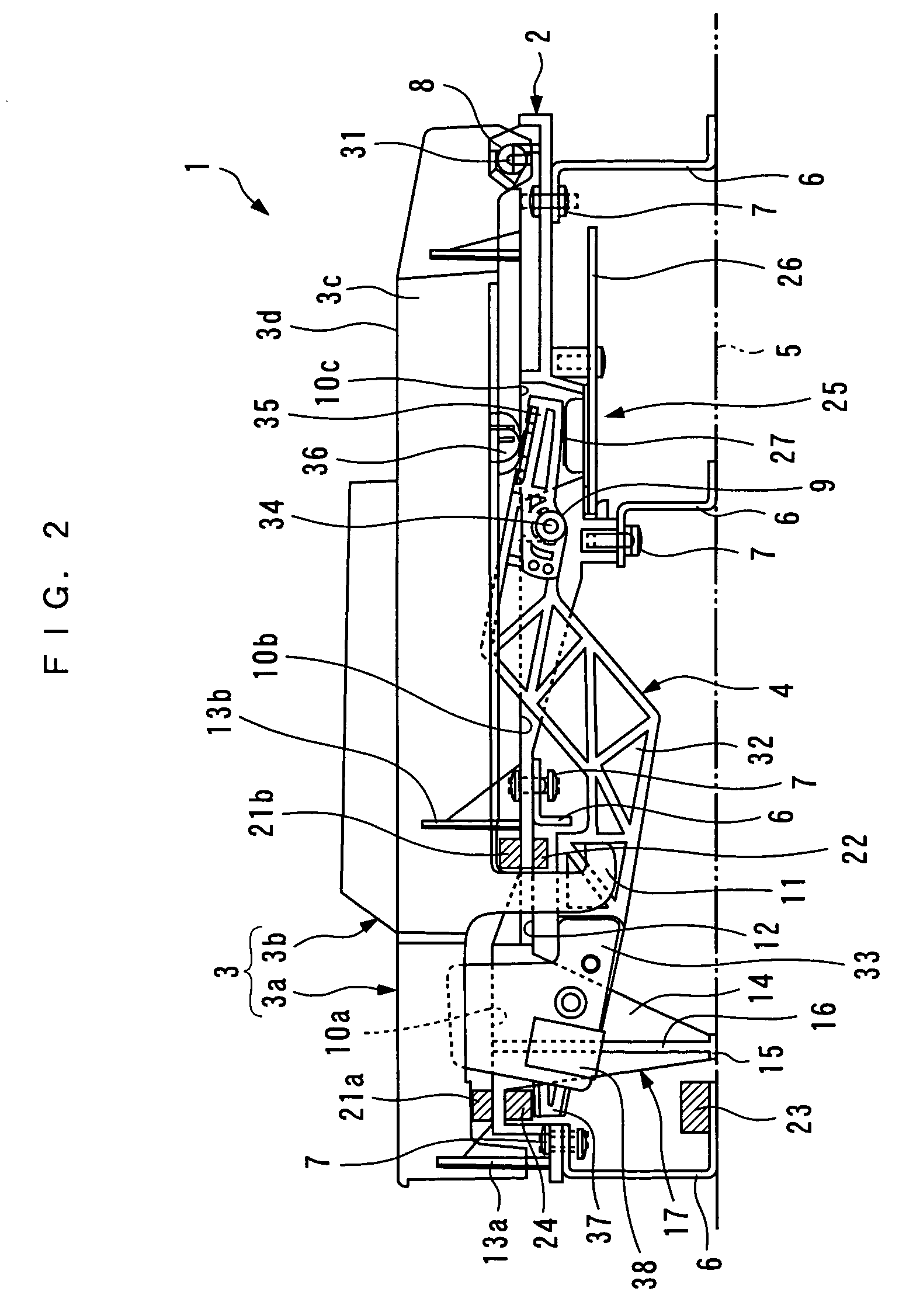
[0085]FIGS. 7 and 8 show a keyboard device for an electronic piano, according to the second embodiment of the present invention. The keyboard device 1′ is for use in an 88-key piano, and includes a chassis assembly 2′, 88 keys 3 comprised of white keys 3a (only one which is shown) and black keys 3b (only one which is shown) pivotally mounted on the rear end of the chassis assembly 2′, and hammers 4 pivotally mounted to the central portion of the chassis assembly 2′.

[0086]The chassis assembly 2′ is constituted by a total of eight chassis: six basic chassis 2a′ (only one of which is shown in FIG. 9A), a chassis 2c, shown in FIG. 13, for the lowest pitch range, and a chassis 2b′, shown in FIG. 14, for the highest pitch range, and the eight chassis are supported on a keybed 5 in a state arranged side by side in the left-right direction.

[...


PUM


Abstract

A keyboard instrument which is capable of ensuring sufficient strength of neighboring portions of chassis and preventing generation of noise, while restricting lateral motion of hammers. Keys are pivotally supported by chassis arranged side by side in a left-right direction. Hammers are pivotally supported by the chassis, for each being pivotally moved in accordance with depression of the associated key. Guides are formed in the chassis and each have a pair of left and right sidewalls opposed to the associated hammer from opposite sides, for restricting lateral motion of the associated hammer. Out of the guides, one at a boundary of each adjacent two of the chassis has the pair of sidewalls formed by an end sidewall of one of the adjacent two chassis and an end sidewall of the other of the same.

Description

BACKGROUND OF THE INVENTION[0001]1. Field of the Invention[0002]This invention relates to a keyboard device for a keyboard instrument, such as an electronic piano.[0003]2. Description of the Prior Art[0004]Conventionally, this kind of keyboard device has been proposed e.g. in Japanese Laid-Open Patent Publication (Kokai) No. 2000-122654. This keyboard device is for use in an electronic piano, and as shown in FIG. 15, it includes a chassis assembly 81, a plurality of keys 82 (only one of which is shown) and a plurality of hammers 83 (only one of which is shown). The chassis assembly 81 is comprised of six intermediate chassis 81a (see FIG. 16) each provided as a unit for one octave, a chassis (not shown) for the lowest pitch range, and a chassis (not shown) for the highest pitch range, which are formed by injection molding of a synthetic resin, such as an ABS resin. The intermediate chassis 81a are identical in size and shape. These eight chassis are connected by four connecting bars...

Claims


Application Information

Patent Timeline
Patent Type & Authority Patents(United States)
IPC IPC(8): G10C3/12G10C3/02G10D1/00
CPCG10C3/12
Inventor SHIMODA, YOSHIAKI
Owner KAWAI MUSICAL INSTR MFG CO
Why Eureka
Try Eureka