Centrifugal separator

Active Publication Date: 2007-05-24
ALFA LAVAL CORP AB
View PDF9 Cites 6 Cited by
  • Summary
  • Abstract
  • Description
  • Claims
  • Application Information

AI Technical Summary

Benefits of technology

[0006] The object of the present invention is to remedy the problems mentioned above and to enable an improved cleaning of the ce

Problems solved by technology

Such an automatic flow control creates a throttling of the flow without leading to a too small flow area which could involve a risk for clogging of the nozzle

Method used


Image

  • Centrifugal separator
  • Centrifugal separator
  • Centrifugal separator

Examples


Embodiment Construction

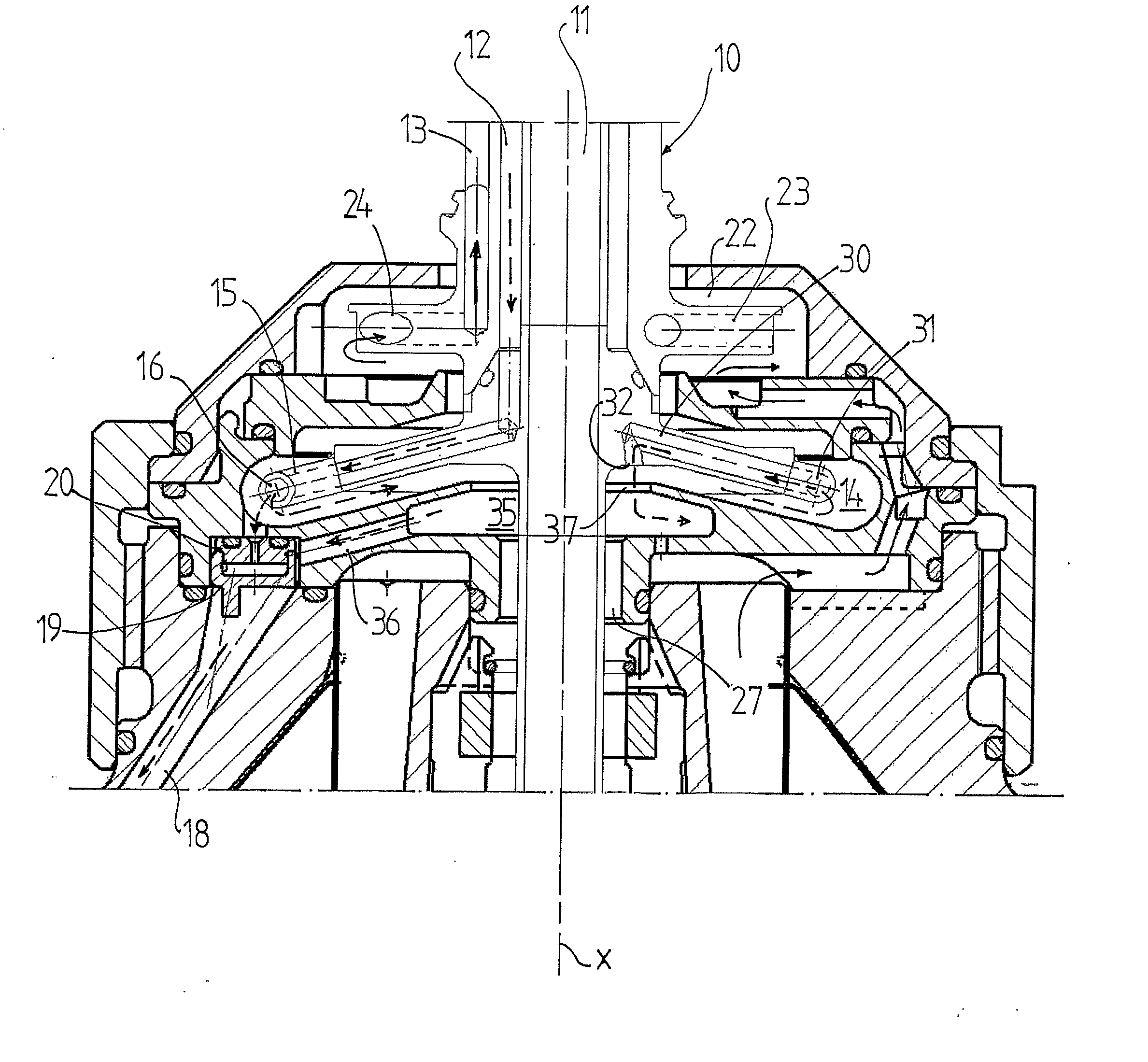
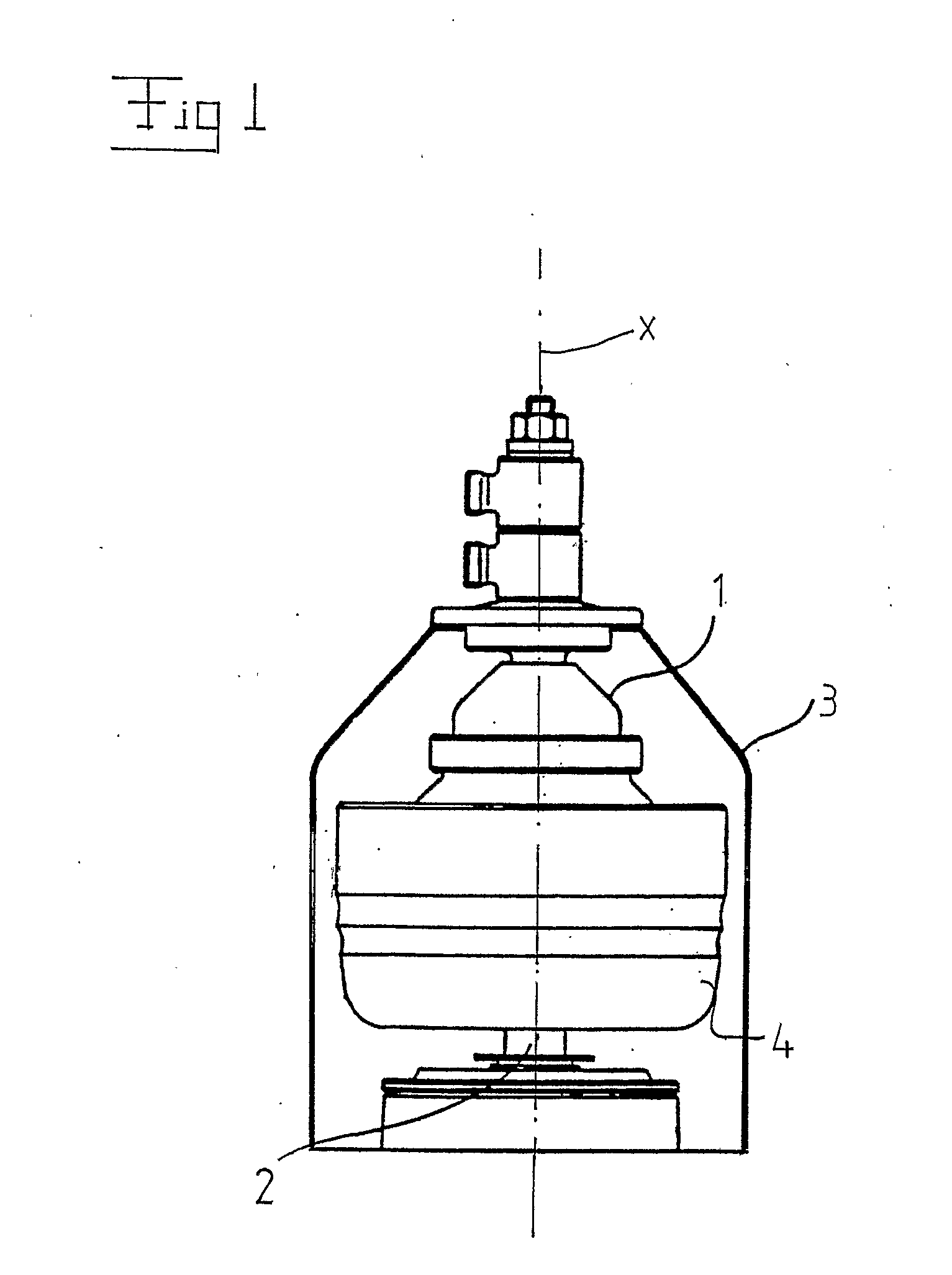
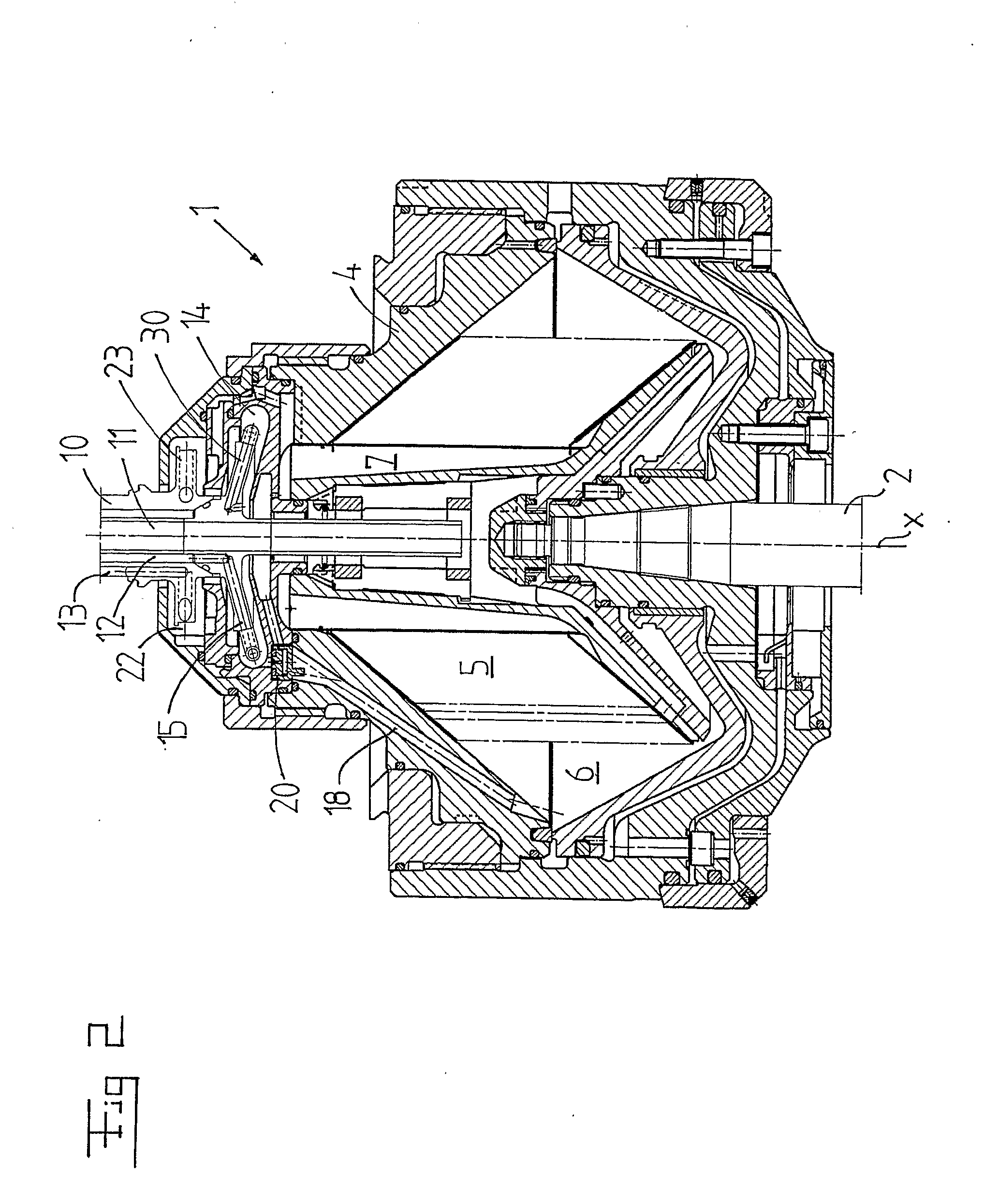
[0018]FIG. 1 discloses a centrifugal separator for separating, during an operation state, a product to a relatively heavy phase and a relatively light phase. The centrifugal separator includes a centrifuge rotor 1, which in the following is called the rotor 1 and which is carried by a substantially vertical spindle 2. The spindle 2 with the rotor 1 is rotatable about a rotary axis x during said operation state. Furthermore, the centrifugal separator includes a substantially stationary frame which is illustrated by and includes a casing 3 for the rotor 1. The spindle 2 is journalled in said frame by means of an upper and a lower bearing, not disclosed. Furthermore, the spindle 2 is connected to a drive member, not disclosed, which is arranged to a rotate the rotor 1 at a high rotary speed during said operation state.

[0019] The rotor 1 includes a rotor wall 4, which defines an outer periphery of the rotor 1 and includes an inner space forming a separating space 5, see FIG. 2. During ...


PUM


Abstract

In a centrifugal separator for separating a product to a heavy phase and a light phase. The centrifuge rotor encloses a separating space. An inlet channel permits feeding of the product to the separating space. A first outlet channel permits discharge of the heavy phase from the separating space. The second outlet channel permits discharge of the light phase from the separating space. The centrifuge rotor includes a first chamber for collecting the heavy phase, a heavy phase channel, for feeding the heavy phase, and a nozzle member between the heavy phase channel and the first chamber for controlled feeding. The first paring member extends outwardly in the first chamber from the first outlet channel for discharge of the heavy phase. The second paring member extends outwardly in the first chamber.

Description

FIELD OF THE INVENTION [0001] The present invention refers to a centrifugal separator for separating a product to at least a relatively heavy phase and a relatively light phase, wherein the centrifugal separator includes a centrifuge rotor, which is rotatable about a rotary axis and includes a rotor wall enclosing a separating space, at least an inlet channel, which extends through the rotor wall and is arranged to permit, during an operation state for the centrifugal separator, feeding of the product to the separating space, a first outlet channel, which extends through the rotor wall and is arranged to permit, during said operation state, discharging of the heavy phase from the separating space, and a second outlet channel, which extends through the rotor wall and is arranged to permit, during said operation state, discharging of the light phase from the separating space, wherein the centrifuge rotor includes a first chamber for collecting the heavy phase, at least one heavy phase...

Claims


Application Information

Patent Timeline
IPC IPC(8): B04B11/08B04B15/06B04B1/08
CPCB04B1/08B04B11/082B04B15/06
Inventor PITKAMAKI, JOUKOSANDBLOM, ROBERT
Owner ALFA LAVAL CORP AB
Why Eureka
Try Eureka