Conductor cleaning system and method

Inactive Publication Date: 2010-07-22
ELECTRIC POWER RES INST INC
View PDF18 Cites 1 Cited by
  • Summary
  • Abstract
  • Description
  • Claims
  • Application Information

AI Technical Summary

Benefits of technology

[0010]According to another aspect of the present invention, a method of cleaning an electrical conductor includes providing a conductor cleaning system having a container and an agitator. The method further includes providing a cleaning solution for cleaning of the electrical co

Problems solved by technology

In current power transmission systems, failures can pose a significant risk to the reliability of the system.
There are several factors that contribute to these failures—one such factor is the failure of compression connectors.
Current data suggests that a primary root cause for failures in compression connectors is improper installation.
Examples of improper installation include lack of compound, alignment, wrong die, and poor cleaning of the aluminum strands of the conductor prior to installation of compression connectors.
Cyclical variations of load current feeding through the increased resistance of the splice-

Method used


Image

  • Conductor cleaning system and method
  • Conductor cleaning system and method
  • Conductor cleaning system and method

Examples


Embodiment Construction

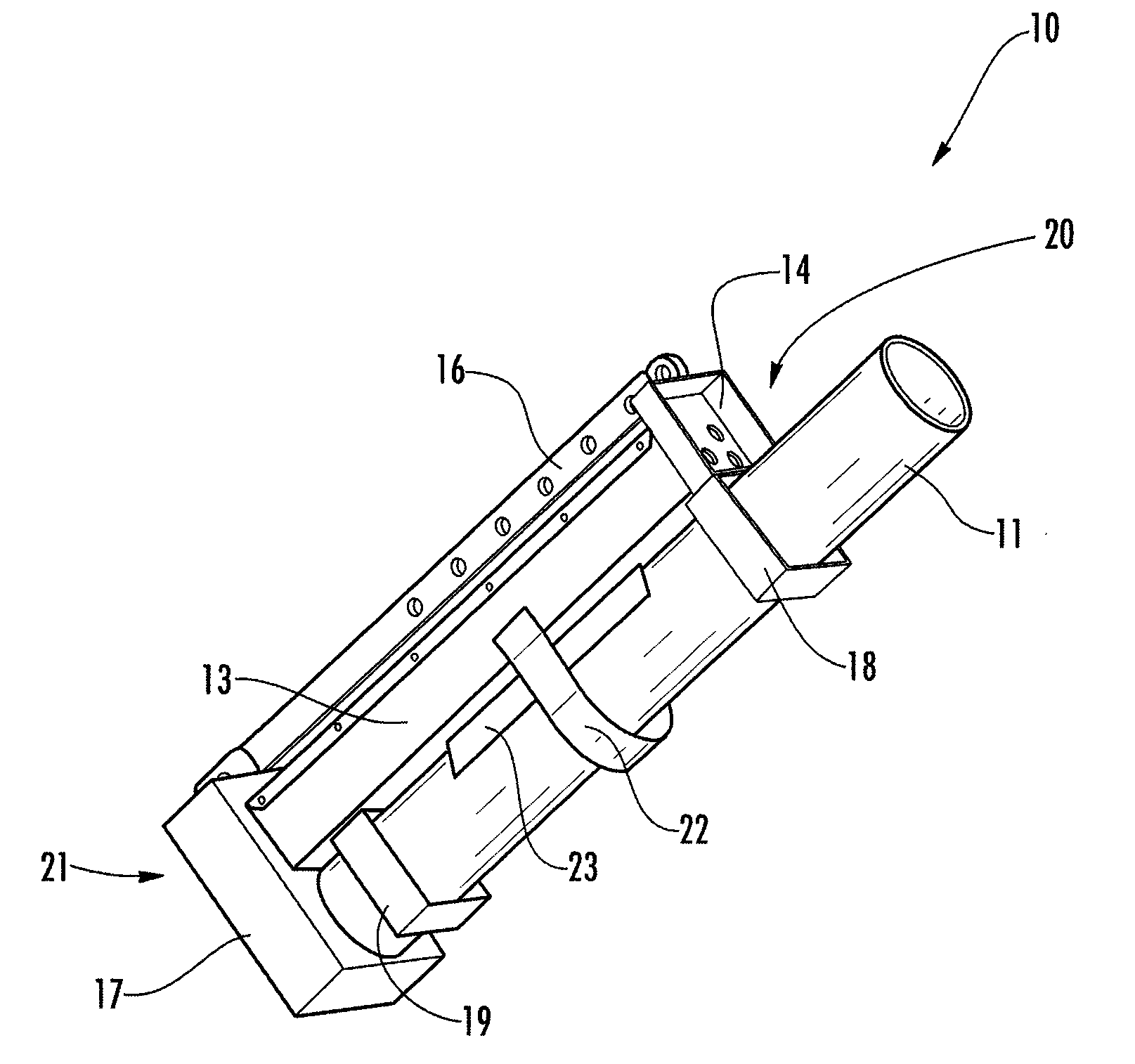
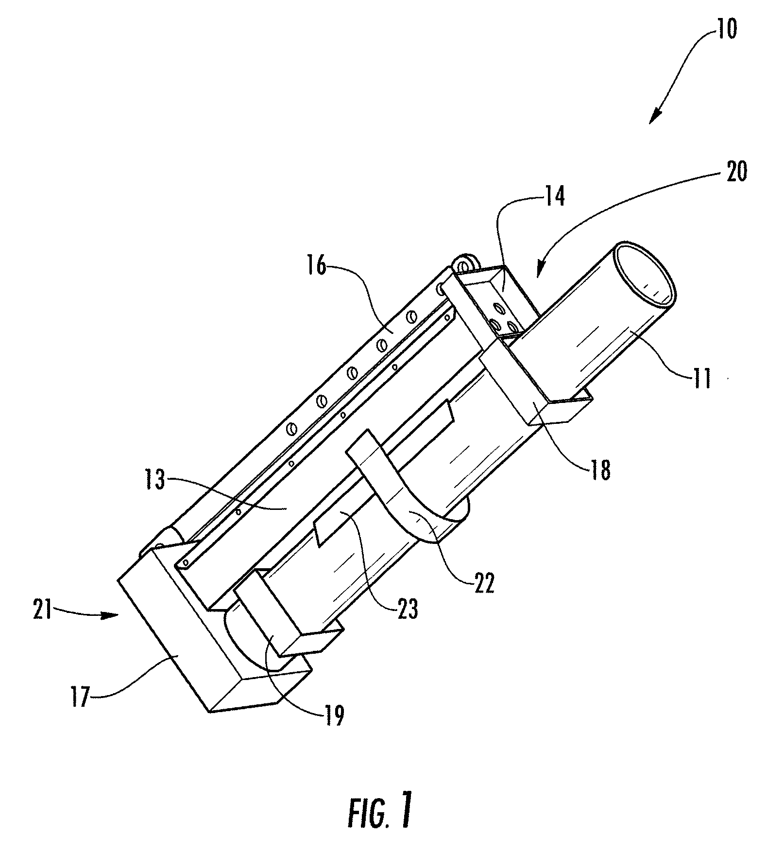
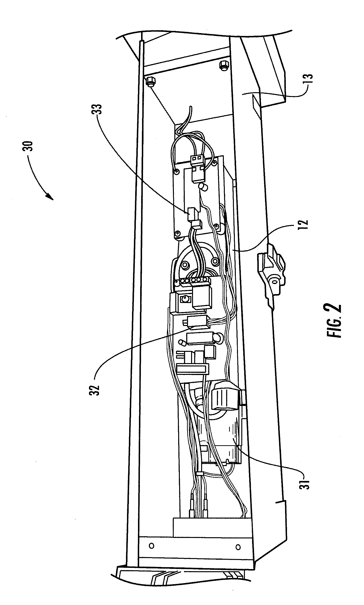
[0024]Referring to the drawings, an exemplary conductor cleaning system according to the present invention is illustrated in FIG. 1 and shown generally at reference numeral 10. The system 10 includes a container, such as tube 11 operably connected to an agitator, such as vibrator 12, FIG. 2, contained in a vibrator housing 13, and a control panel 14 for controlling the system 10. The container 11 may be disposable or permanently attached to the system 10.

[0025]The vibrator housing 13 is adapted to receive and support the container 11, and includes an attachment rail 16 to allow the system 10 to be attached to a support for easy operation or to allow a user to easily carry the system 10. Other attachments such as a hook-type attachment may also be used to attach the system 10 to a bucket of a bucket truck or other suitable support. A standing base 17 is disposed at one end of the housing 13 to allow the system 10 to be positioned in a stand-up position such that the tube 11 is in a v...


PUM

PropertyMeasurementUnit
Lengthaaaaaaaaaa
Weightaaaaaaaaaa
Solubility (mass)aaaaaaaaaa

Abstract

A conductor cleaning system for cleaning aluminum strands of all aluminum and steel reinforced conductors, such as ACSS, ACSR, ACAR, and AAA. The conductor cleaning system having a container adapted to receive a portion of a conductor to be cleaned, a housing adapted to receive and support the container, and a cleaning solution contained in the container for cleaning the portion of the conductor. The cleaning solution being adapted to clean the conductor without reacting with or damaging the conductor.

Description

[0001]This application is a Continuation-In-Part of U.S. patent application Ser. No. 12 / 357,610 filed on Jan. 22, 2009.BACKGROUND OF THE INVENTION[0002]The present invention relates generally to a conductor cleaning system, and more particularly to a system for cleaning aluminum strands of all aluminum and steel reinforced electrical conductors, such as ACSS, ACSR, ACAR, and AAA.[0003]In current power transmission systems, failures can pose a significant risk to the reliability of the system. There are several factors that contribute to these failures—one such factor is the failure of compression connectors.[0004]Current data suggests that a primary root cause for failures in compression connectors is improper installation. Examples of improper installation include lack of compound, alignment, wrong die, and poor cleaning of the aluminum strands of the conductor prior to installation of compression connectors. Research indicates that corrosion products and other contaminants (result...

Claims


Application Information

Patent Timeline
IPC IPC(8): C23G1/02
CPCB08B3/123C11D7/06C11D7/10B08B13/00C11D11/0041B08B3/102C11D7/14
Inventor PHILLIPS, ANDREW J.STEWART, ANDREW H.NINGILERI, SHRIDASHURST, NEIL J.BUSH, J. FINLEYXIA, SIKEXIAO, CHENGHELIU, YANSHENG
Owner ELECTRIC POWER RES INST INC
Why Eureka
Try Eureka