

Positioning equipment in hardware tool polishing machine
A technology for positioning equipment and hardware tools, used in metal processing equipment, grinding/polishing equipment, surface-polished machine tools, etc. It can solve the problems of coolant adhesion and inability to effectively discharge it to the outside, and achieve the effect of increasing the degree of cleaning.
- Summary
- Abstract
- Description
- Claims
- Application Information
AI Technical Summary
Problems solved by technology
Method used
Image

Examples
Embodiment 1
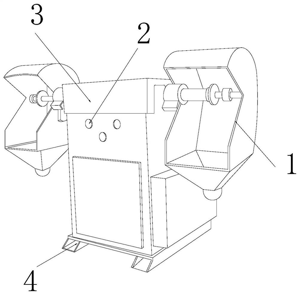
[0025] as attached figure 1 to attach Figure 5 Shown:
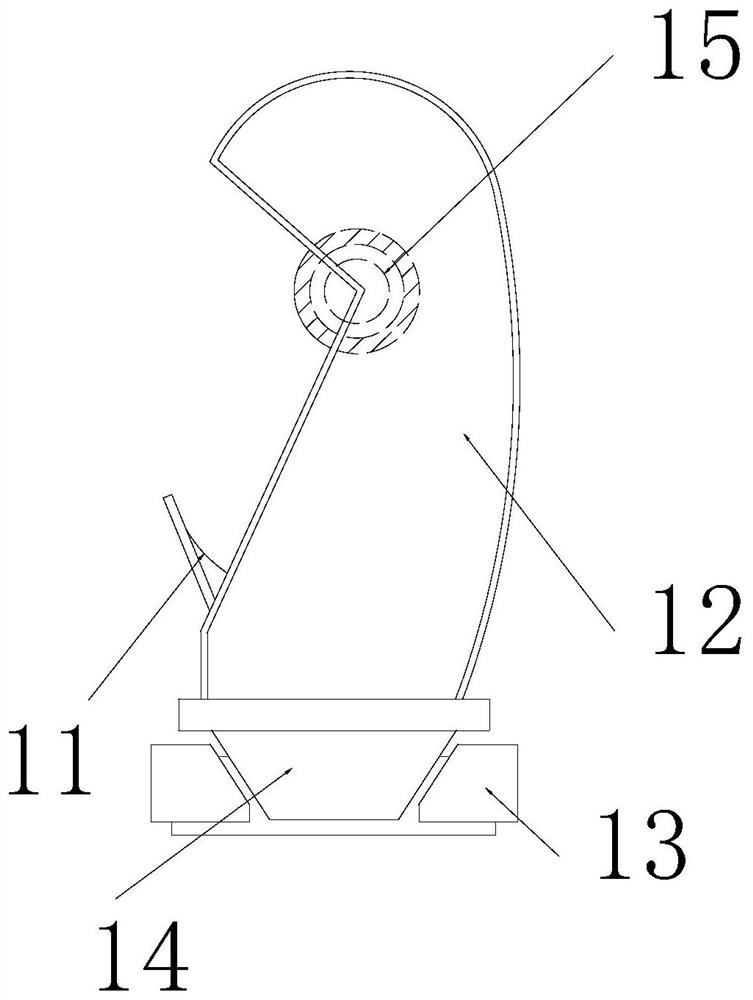
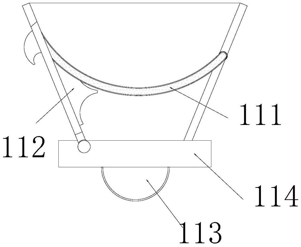
[0026] The invention provides a positioning device in a hardware tool polishing machine, the structure of which includes a polishing device 1, a start button 2, a body 3, and a bracket 4. The polishing device 1 is symmetrically installed on the left and right sides of the body 3, and the start button 2 is inlaid on the outer end surface of the body 3, the lower end surface of the body 3 is fixed with a bracket 4 by welding, and the bracket 4 is located directly below the start button 2; the polishing device 1 includes a collection mechanism 11, a protective shell 12, a second An embedding plate 13, a cover shell 14, and a polishing machine 15, the collection mechanism 11 is embedded directly below the polisher 15, the protective shell 12 is installed directly above the cover shell 14 by welding, and the first embedded The fixing plates 13 are inlaid on the left and right ends of the cover shell 14 , and the cover shell...
Embodiment 2
[0033] as attached Image 6 to attach Figure 7 Shown:
[0034] Wherein, the collection ball 113 includes a nested tube 131, an inclined-plane block 132, an adsorption magnetic ring 133, a hollow ball 134, and a rubber ball 135. The nested tube 131 is inlaid on the lower surface of the rubber ball 135, and the inclined-plane block 132 is symmetrically installed on the left and right sides of the upper end of the magnetic adsorption ring 133, the magnetic adsorption ring 133 is located directly below the nesting tube 131, the hollow ball 134 is wrapped around the outer end surface of the rubber ball 135, and the rubber ball 135 is located at Directly above the slope block 132, the slope block 132 is provided with two left and right sides, and an arc chamfer is provided between the adjacent end faces of the two, so that the nested pipe 131 can be moved along with the surface friction of the slope block 132 The arc chamfering of the inclined block 132 is inserted into the magneti...
PUM
 Abstract
Description
Claims
Application Information