Wire guide having distal coupling tip

a wire guide and distal coupling technology, applied in the field of wire guides, can solve the problems of proximal tortuosity of the vasculature, wire guide tip may prolapse away from the site, wire guide requirements subject to potentially conflicting requirements, etc., and achieve the effect of easily and reliably traversing the vasculatur

Active Publication Date: 2007-05-24
COOK MEDICAL TECH LLC
View PDF99 Cites 4 Cited by
  • Summary
  • Abstract
  • Description
  • Claims
  • Application Information

AI Technical Summary

Benefits of technology

[0008] The present invention provides a supporting wire guide for intracorporeal procedures that may be easily and reliably traversed through the vasculature to a position proximate a previously introduced wire guide. The supporting wire guide is a coupling wire guide that is structured to be slidably coupled to the previously introduced wire guide. In one embodiment constructed in accordance with the teachings of the present invention, the coupling w

Problems solved by technology

Proximal tortuosity of the vasculature is problematic for all medical catheter devices such as atherectomy devices, angioplasty devices, stent delivery devices, and filter delivery devices.
Accordingly, wire guides are subjected to potentially conflicting requirements.
However, in some situations the wire guide tip may prolapse away from the site to which it is guiding the device.
For example, balloon angioplasty in vessels with proximal tortuosity has been associated with a higher incidence of acute complications and procedural failure due to the inability to cross lesions with a conventional floppy wire guide, and due to the inability of the wire guide to provide adequate support to the balloon catheter.
Heavy-duty wire guides, on the other hand, are generally not well suited as primary wire guides because of their stiffness and potential for causing injury to the vesse

Method used


Image

  • Wire guide having distal coupling tip
  • Wire guide having distal coupling tip

Examples


Embodiment Construction

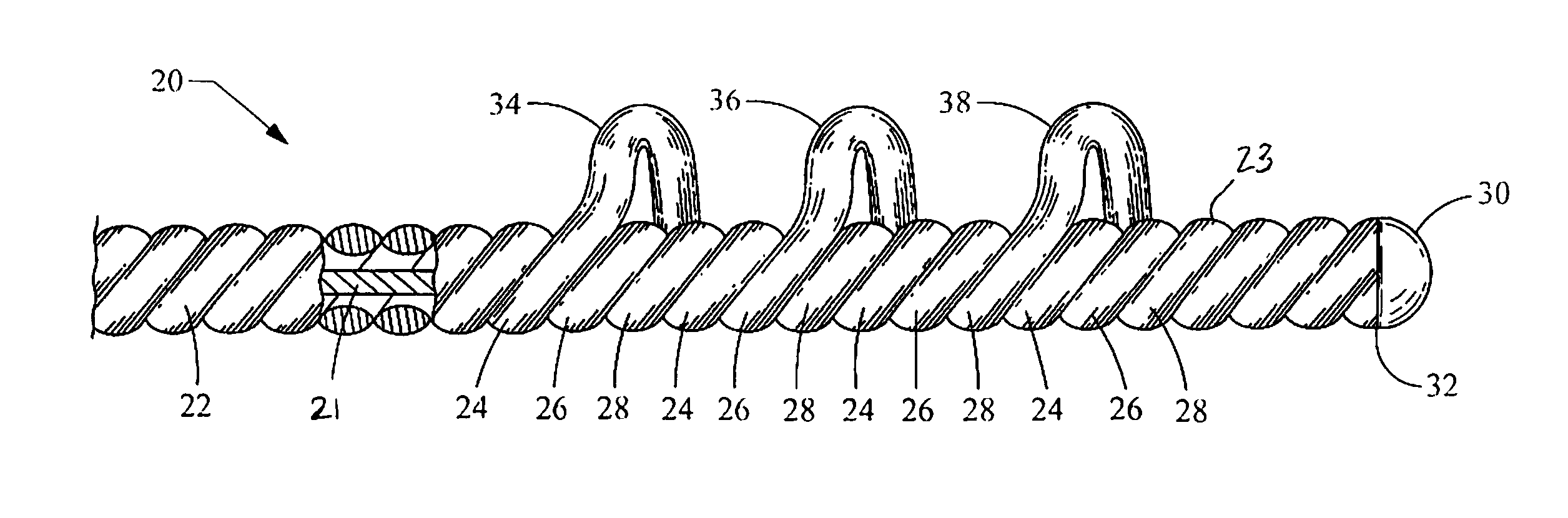
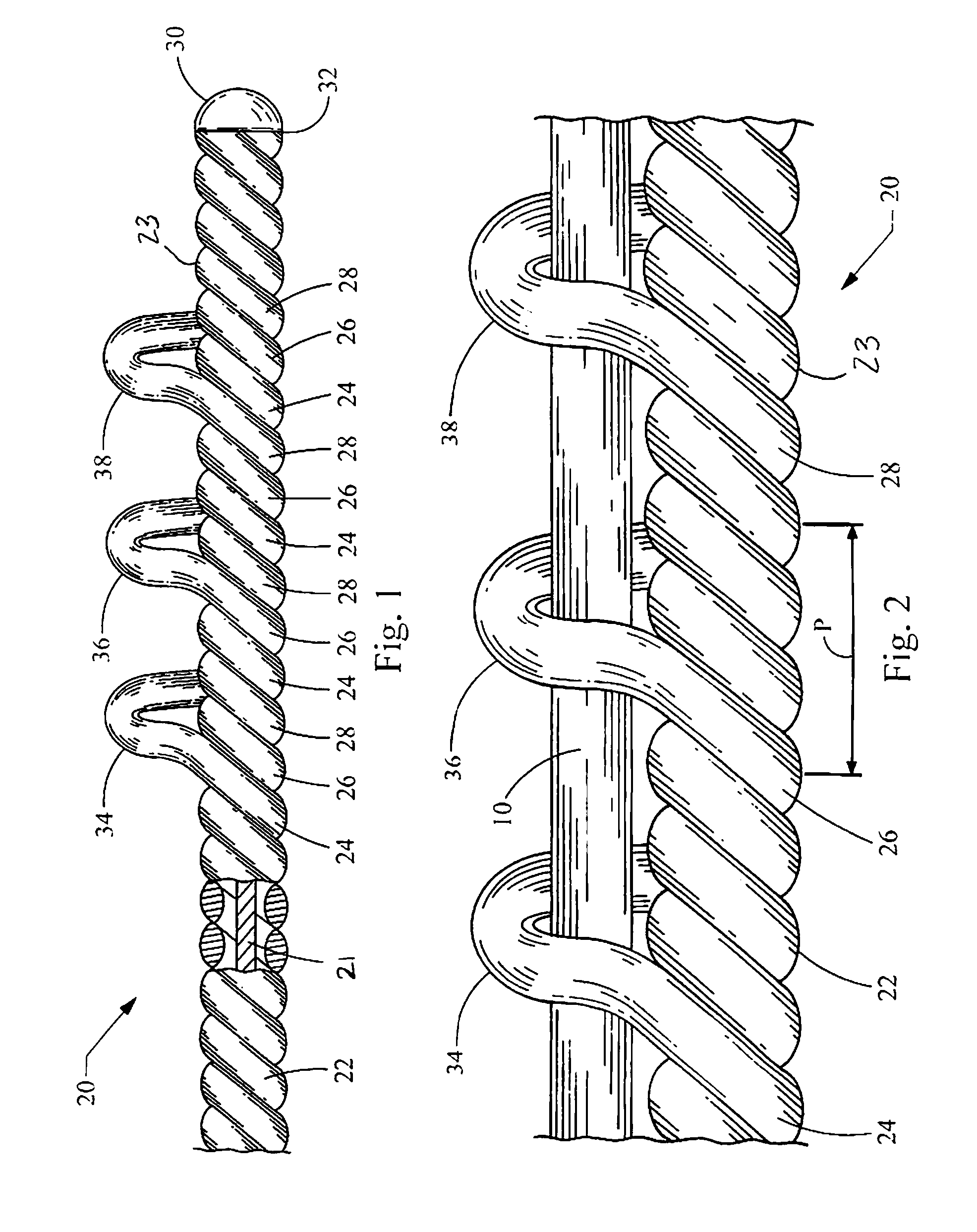
[0014] Turning now to the figures, FIGS. 1 and 2 depict a coupling wire guide 20 constructed in accordance with the teachings of the present invention. The coupling wire guide 20 includes a main body 22 having a distal portion 23. The main body 22, including the distal portion 23, is defined by a first wire 24, a second wire 26, and a third wire 28. The first, second and third wires 24, 26, 28 are disposed over a safety wire 21, which in turn is connected to an end cap 30 defining a distal tip 32 of the coupling wire guide 20. Particularly, the first, second and third wires 24, 26, 28 are wound around the safety wire 21, preferably by coiling the wires in parallel to form three phases or filars. It can be seen in the figures that the wires 24, 26, 28 are immediately adjacent each other in the wind.

[0015] The coupling wire guide 20 is structured for coupling to a previously introduced wire guide 10, depicted as a solid wire in FIG. 2. While wire guides are often used in percutaneous...


PUM


Abstract

A coupling wire guide generally includes a main body defined by a first wire wound around a safety wire. A first loop is defined by an enlarged revolution of the first wire within a distal portion of the main body. The first loop is sized to receive a previously introduced wire guide for coupling the two wire guides.

Description

CROSS-REFERENCE TO RELATED APPLICATIONS [0001] This application claims the benefit of U.S. Provisional Application Ser. No. 60 / 730,776 filed on Oct. 27, 2005, entitled “WIRE GUIDE HAVING DISTAL COUPLING TIP, the entire contents of which are incorporated herein by reference.FIELD OF THE INVENTION [0002] This invention relates generally to a wire guide for use in intracorporeal procedures, and more particularly relates to the construction of a wire guide to be coupled to a previously introduced wire guide for assistance during interventional procedures in vessels with proximal tortuosity, or as a more substantial wire guide for angioplasty procedures, stenting procedures, and other device placement procedures and their related devices. BACKGROUND OF THE INVENTION [0003] Proximal tortuosity of the vasculature is problematic for all medical catheter devices such as atherectomy devices, angioplasty devices, stent delivery devices, and filter delivery devices. Wire guides are therefore ty...

Claims


Application Information

Patent Timeline
IPC IPC(8): A61M25/00
CPCA61M25/09A61M25/0905A61M2025/09083A61M2025/09175A61M2025/09183
Inventor MELSHEIMER, JEFFRY S.
Owner COOK MEDICAL TECH LLC
Why Eureka
Try Eureka