Wire guide having distal coupling tip for attachment to a previously introduced wire guide

a wire guide and distal coupling technology, which is applied in the direction of contact members penetrating/cutting insulation/cable strands, catheters, applications, etc., can solve the problems of proximal tortuosity of the vasculature, wire guide tip prolapse from the site, and potential conflicting requirements for wire guide requirements, etc., to achieve easy and reliable traversal

Active Publication Date: 2010-09-21
COOK MEDICAL TECH LLC
View PDF130 Cites 8 Cited by
  • Summary
  • Abstract
  • Description
  • Claims
  • Application Information

AI Technical Summary

Benefits of technology

[0008]The present invention provides a supporting wire guide for intracorporeal procedures that may be easily and reliably traversed to a position proximate a previously introduced wire guide. The supporting wire guide is a coupling wire guide that is structured to be slidably coupled to the previously introduced wire guide. In one embodiment constructed in accordance with the teachings of the present invention, the coupling wire guide generally includes a main body having a distal end and a coupling tip connected to the distal end. The coupling tip includes a coupling portion defining a coupling passageway having a proximal port and a distal port. A slot is formed in the coupling tip and is in communication with the coupling passageway. The slot extends from the proximal port to the distal port, thereby permitting the coupling wire guide to be “clipped-on” to the mid-section of the previously introduced wire guide or any location having the most efficacy.

Problems solved by technology

Proximal tortuosity of the vasculature is problematic for all medical catheter devices such as atherectomy devices, angioplasty devices, stent delivery devices, and filter delivery devices.
Accordingly, wire guides are subjected to potentially conflicting requirements.
However, in some situations the wire guide tip may prolapse from the site to which it is guiding the device.
For example, balloon angioplasty in vessels with proximal tortuosity has been associated with a higher incidence of acute complications and procedural failure due to the inability to cross lesions with a conventional floppy wire guide, and due to the inability of the wire guide to provide adequate support to the balloon catheter.
Heavy-duty wire guides, on the other hand, are generally not well suited as primary wire guides because of their stiffness and potential for causing injury to the vessel during introduction.
However, the navigation of the supplemental wire guide parallel to the first wire guide is an exacting and time consuming process in which additional difficulties are encountered.
For example, the second wire guide can cork screw or coil around the first wire guide, which may result in immobilization or unintended movement of the first wire guide, which in turn may require the retraction and re-feeding of the supplemental wire guide and / or the primary wire guide.
Moreover, if retraction of the supplemental wire guide is necessary, either of the wire guides may become contaminated and the entire process may need to be restarted with sterile components.
Additionally, when traversing through the heart of a patient, and particularly the ostium, the larger open space of the heart makes identical placement of the supplemental wire guide somewhat difficult.

Method used


Image

  • Wire guide having distal coupling tip for attachment to a previously introduced wire guide
  • Wire guide having distal coupling tip for attachment to a previously introduced wire guide
  • Wire guide having distal coupling tip for attachment to a previously introduced wire guide

Examples


Embodiment Construction

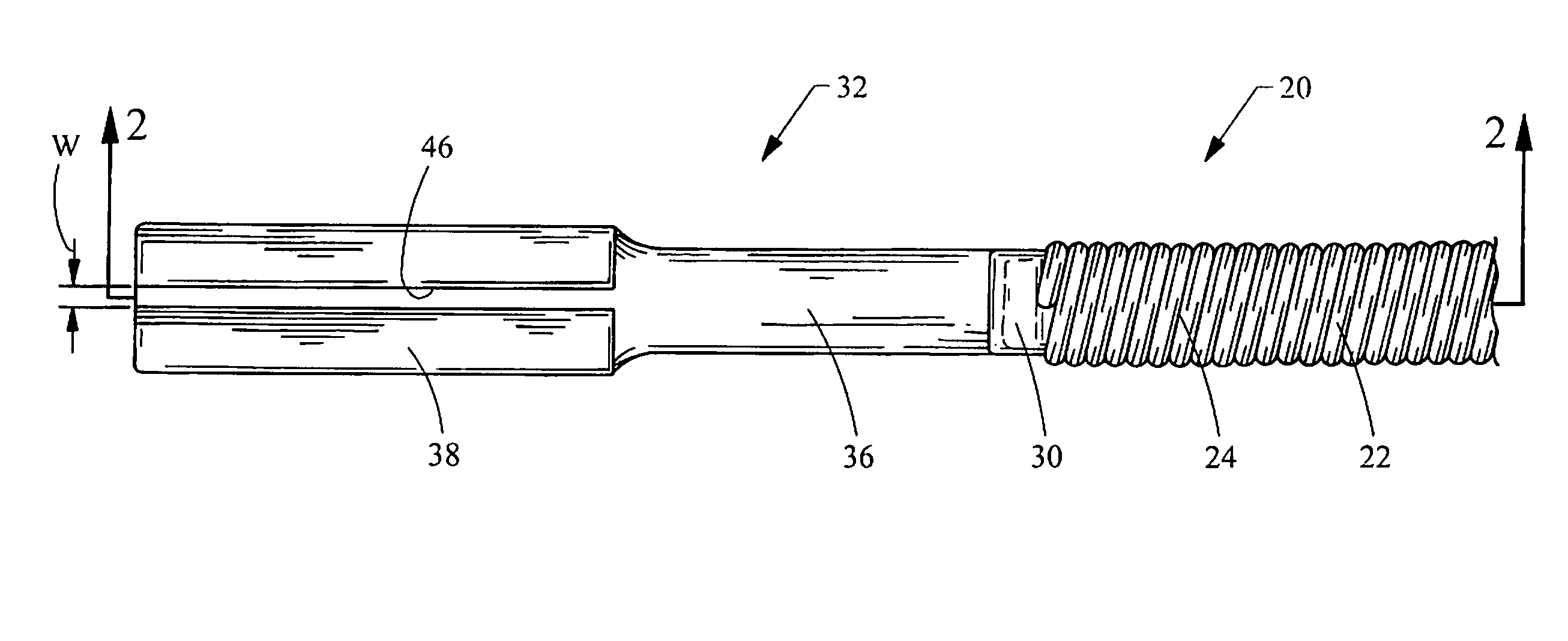
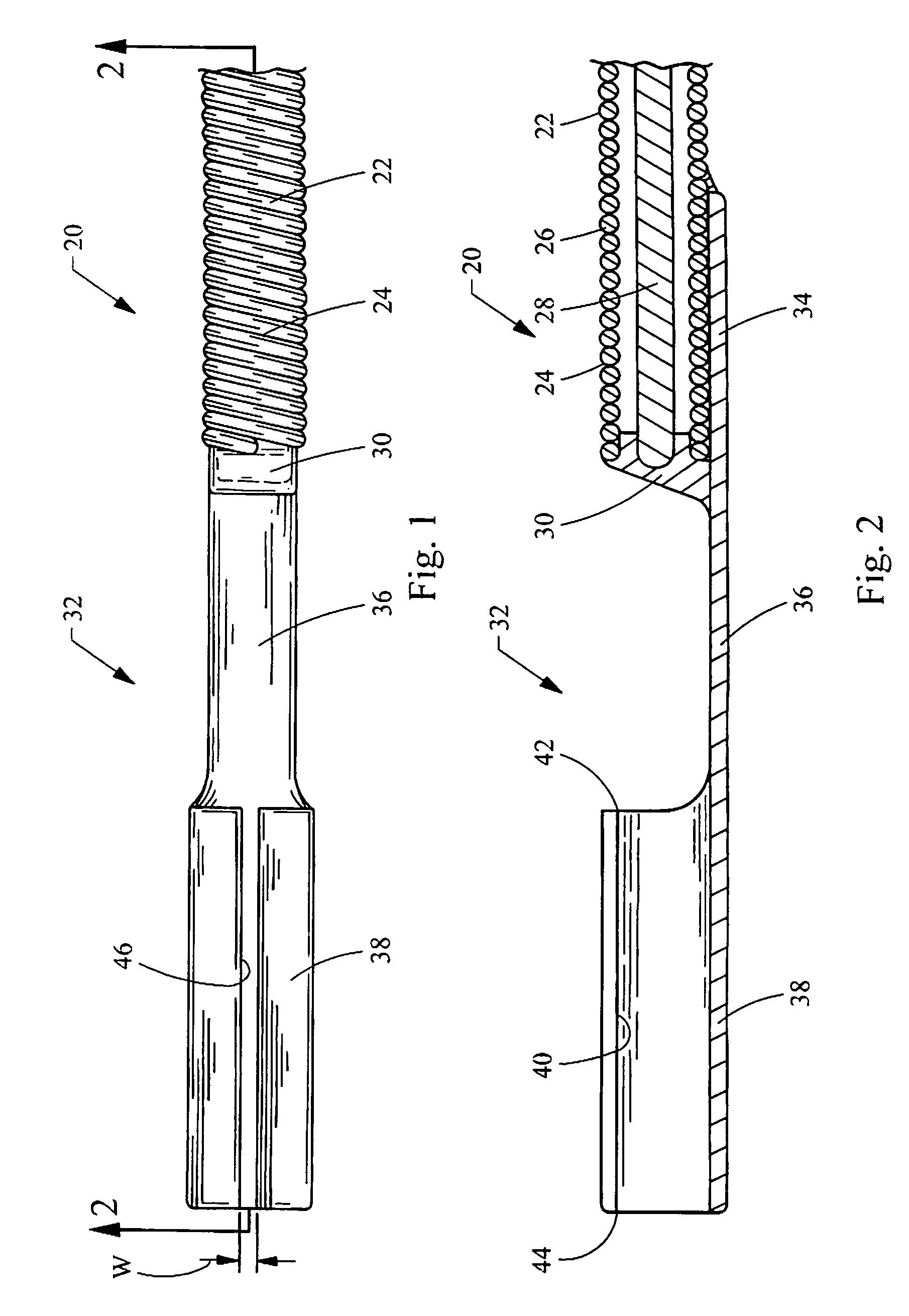
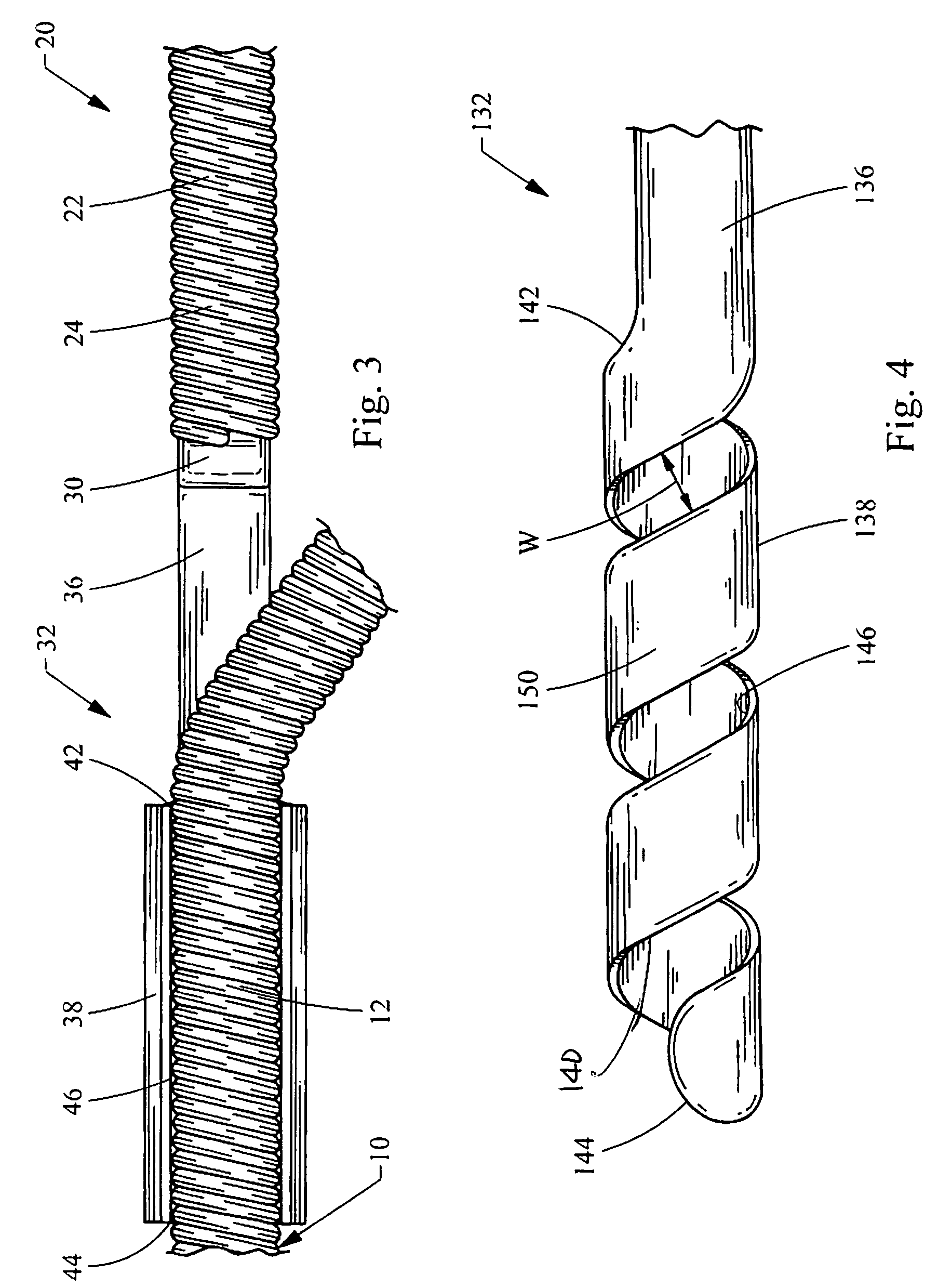
[0021]Turning now to the figures, FIGS. 1 to 3 depict a coupling wire guide 20 constructed in accordance with the teachings of the present invention. The coupling wire guide 20 is easily and reliably coupled to and traversed along a previously introduced wire guide 10 (FIG. 3), and notably is “side-loading” meaning the wire guide 20 may be attached by “clipping on” to a mid-section of the previously introduced wire guide 10. As used herein, the term “mid-section” refers to any point between the free ends of the previously introduced wire guide 10. In this manner, the coupling wire guide 20 may be coupled to and traversed along the previously introduced wire guide 10 without gaining access to the proximal end (or distal end) of the previously introduced guide wire 10, thereby saving time and increasing the versatility of the coupling wire guide 20.

[0022]As best seen in FIGS. 1 and 2, the coupling wire guide 20 generally includes a main body 22 and a coupling tip 32. The coupling tip ...


PUM


Abstract

A coupling wire guide structured to be slidably coupled to a previously introduced wire guide. The coupling wire guide generally includes a main body having a distal end and a coupling tip connection to the distal end. The coupling tip includes a coupling portion defining a coupling passageway having a proximal port and a distal port. A slot is formed in the coupling tip and is in communication with the coupling passageway. The slot extends from the proximal port to the distal port, thereby permitting the coupling wire guide to be “clipped-on” to the mid-section of the previously introduced wire guide or any location having the most efficacy.

Description

CROSS-REFERENCE TO RELATED APPLICATIONS[0001]This application claims the benefit of U.S. Provisional Application Ser. No. 60 / 763,523 filed on Jan. 31, 2006, entitled “WIRE GUIDE HAVING DISTAL COUPLING TIP”, the entire contents of which are incorporated herein by reference.FIELD OF THE INVENTION[0002]This invention relates generally to a wire guide for use in intracorporeal procedures, and more particularly relates to the construction of a wire guide to be coupled to a previously introduced wire guide for assistance during interventional procedures in vessels with proximal tortuosity, or as a more substantial wire guide for angioplasty procedures, stenting procedures, and other device placement procedures and their related devices.BACKGROUND OF THE INVENTION[0003]Proximal tortuosity of the vasculature is problematic for all medical catheter devices such as atherectomy devices, angioplasty devices, stent delivery devices, and filter delivery devices. Wire guides are therefore typicall...

Claims


Application Information

Patent Timeline
Patent Type & Authority Patents(United States)
IPC IPC(8): A61M25/00
CPCA61M25/0905
Inventor MELSHEIMER, JEFFRY S.
Owner COOK MEDICAL TECH LLC
Why Eureka
Try Eureka