Key input apparatus and method

Inactive Publication Date: 2007-06-21
SAMSUNG ELECTRONICS CO LTD
View PDF3 Cites 20 Cited by
  • Summary
  • Abstract
  • Description
  • Claims
  • Application Information

AI Technical Summary

Benefits of technology

[0010]The present general inventive concept provides a key input method for simply a

Problems solved by technology

However, this method is also inconvenient since a user must memorize which funct

Method used


Image

  • Key input apparatus and method
  • Key input apparatus and method
  • Key input apparatus and method

Examples


Embodiment Construction

[0036]Reference will now be made in detail to the embodiments of the present general inventive concept, examples of which are illustrated in the accompanying drawings, wherein like reference numerals refer to the like elements throughout. The embodiments are described below in order to explain the present general inventive concept by referring to the figures.

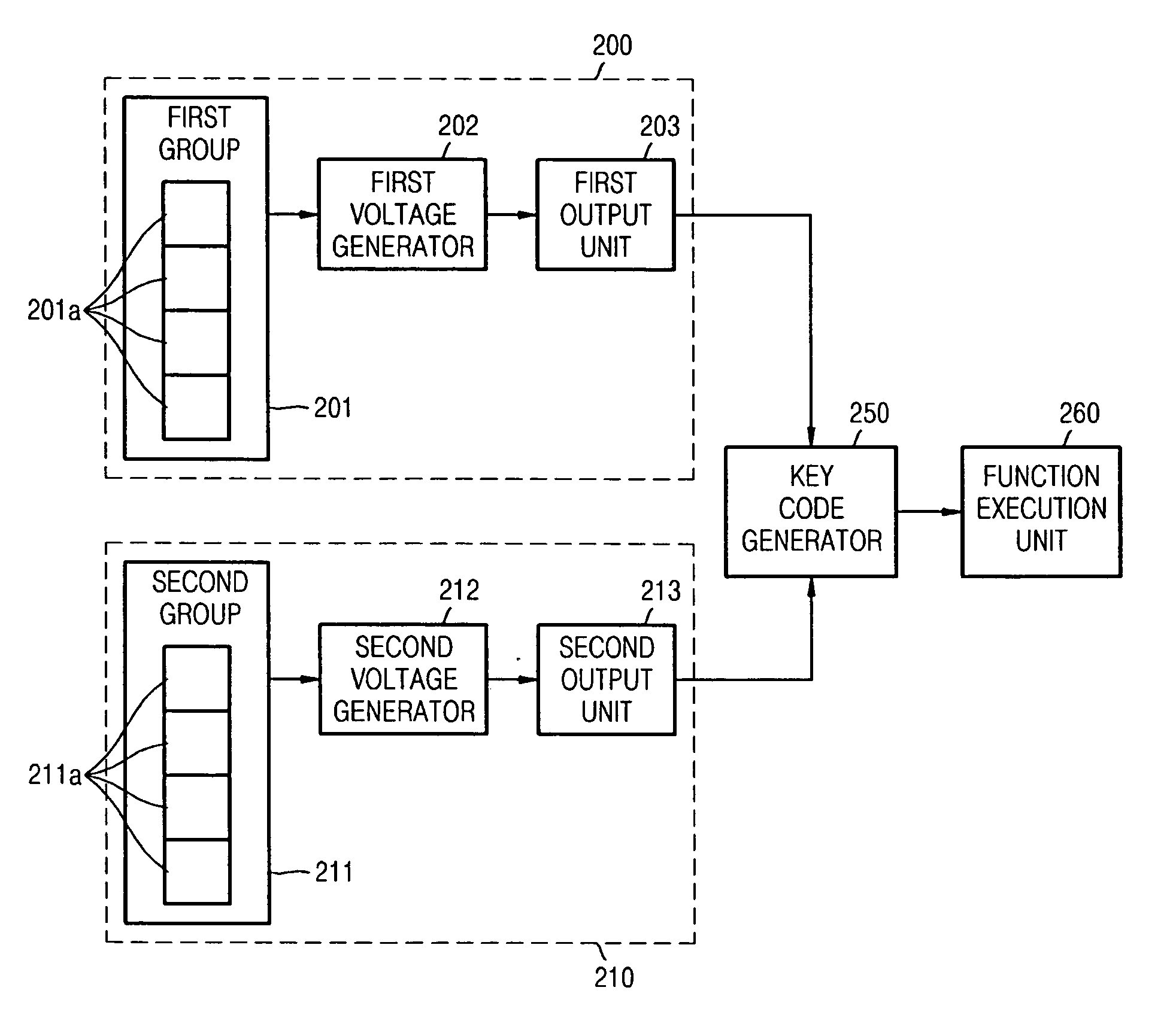
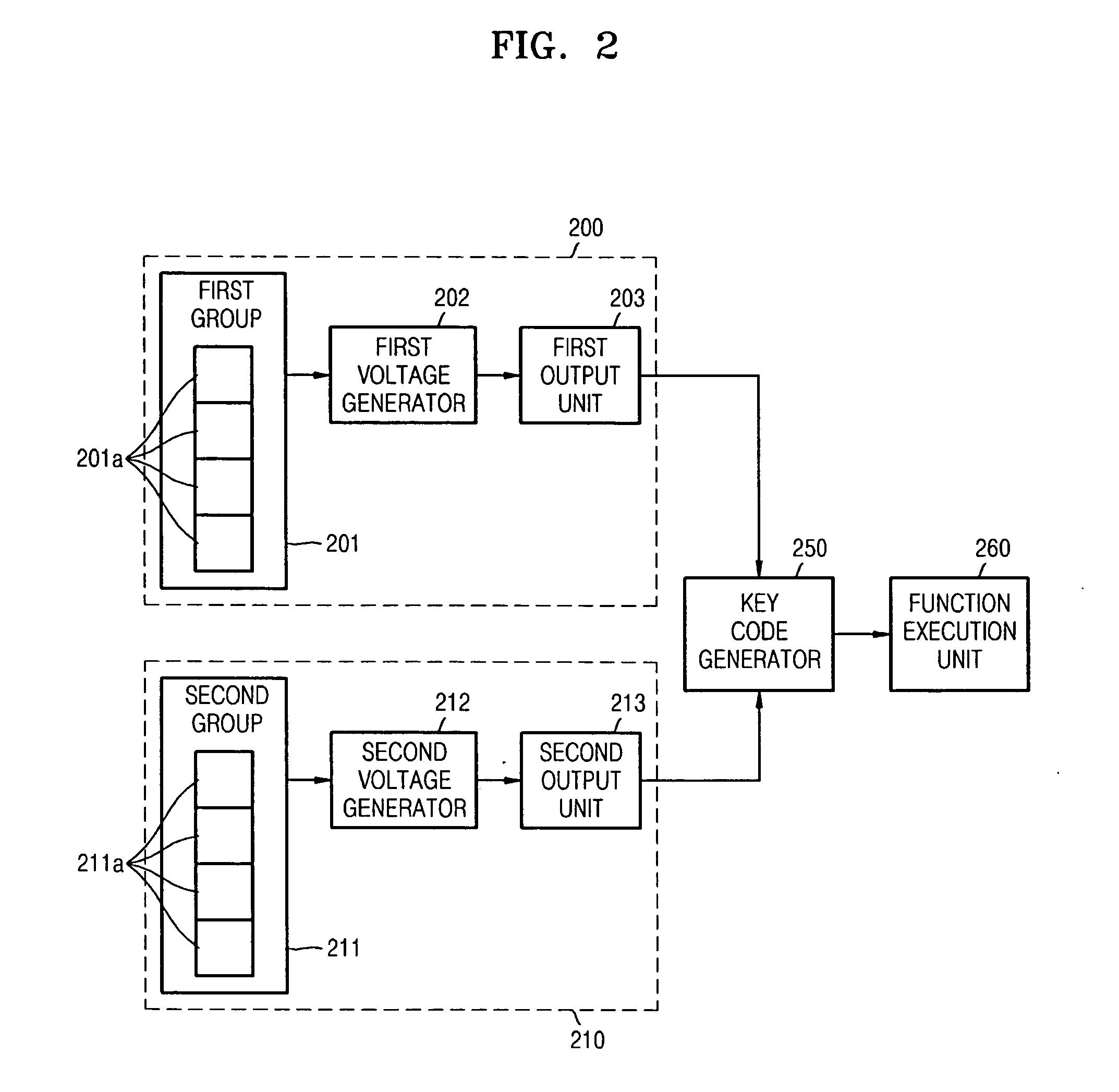
[0037]FIG. 2 is a block diagram illustrating a key input apparatus according to an embodiment of the present general inventive concept.

[0038]Referring to FIG. 2, the key input apparatus includes a first key input unit 200 and a second key input unit 210. When any one of a plurality of first keys 201a of a first group 201 is pressed, the first key input unit 200 outputs first data corresponding to the pressed key. The first key input unit 200 includes the first group 201, a first voltage generator 202, and a first output unit 203. The second key input unit 211 includes a plurality of second keys 211a.

[0039]The first group 201 an...


PUM


Abstract

A key input apparatus and method includes a first key input unit, when any one of a plurality of keys of a first group is pressed, to output first data corresponding to the pressed key, a second key input unit, when any one of a plurality of keys of a second group is pressed, to output second data corresponding to the pressed key, and a key code generator to assign the first data and the second data to a certain row number and a certain column number, respectively, of a matrix and to generate a different key code corresponding to the row number and the column number of the matrix according to an order in which the first data and the second data are output, wherein the keys of the first group are different from the keys of the second group.

Description

CROSS-REFERENCE TO RELATED APPLICATIONS[0001]This application claims priority under 35 U.S.C. §119(a) from Korean Patent Application No. 10-2005-0126931, filed on Dec. 21, 2005, in the Korean Intellectual Property Office, the disclosure of which is incorporated herein in its entirety by reference.BACKGROUND OF THE INVENTION[0002]1. Field of the Invention[0003]The present general inventive concept relates to a key input apparatus, and more particularly, to a key input apparatus and method.[0004]2. Description of the Related Art[0005]A portable device, such as a cellular phone, or a remote controller performs a number of operations with a small number of keys. According to a conventional portable device, a single operation is performed when a single key is pressed.[0006]FIG. 1 is a block diagram illustrated a conventional key input circuit using a matrix scheme.[0007]Referring to FIG. 1, small circles indicate a plurality of keys for inputting data. Each of these keys includes a switc...

Claims


Application Information

Patent Timeline
IPC IPC(8): H03M11/00
CPCG06F1/1626G06F1/1662G06F3/0233G06F3/0236G09G2370/24H03M11/16H03M11/24H03K17/94
Inventor LEE, HYUN-KYU
Owner SAMSUNG ELECTRONICS CO LTD
Why Eureka
Try Eureka