Gaseous fluid generation system

a gaseous fluid and generation system technology, applied in the direction of steam generation using steam absorption, container discharging methods, immersion heating arrangements, etc., can solve the problems of requiring recuperative heating time, affecting the efficiency of existing electric powered steam generation systems and boilers, and prolonging the time required to reach operating temperature at start-up, etc., to achieve low heat capacity of saturated water vapor and high power density

Active Publication Date: 2007-01-09
BETADYNE IND INC
View PDF3 Cites 12 Cited by
  • Summary
  • Abstract
  • Description
  • Claims
  • Application Information

AI Technical Summary

Benefits of technology

[0009]Practice of the present invention can allow cost efficient, convenient generation of gaseous fluids. The gaseous fluid generation system and method for generating a gaseous fluid described herein can be useful for producing gaseous fluids, e.g., steam, on-site and on-demand. In one embodiment, the present invention can be used to produce either saturated or superheated gaseous fluids using the same apparatus.
[0011]Existing electric powered steam generation devices typically contain heaters located at or near the bottom of the reservoir to help provide for total heater liquid immersion during operation. The total immersion heaters, operating at high power density, can burn out upon losing full immersion due to the low heat capacity of saturated water vapor. In contrast, the present invention includes the use of resistive heating elements that have power densities selected to heat liquid fluids and gaseous fluids. In one embodiment, resistive heating elements having power densities selected to heat both liquid fluids and gaseous fluids are contained within the columnar vessel. Thus, the columnar vessel can contain at least one resistive heating element that can operate without overheating in at least two distinctive states of the fluid in the column, i.e., liquid fluid and gaseous fluid.
[0012]Since the present gaseous fluid generation system does not require a holding reservoir, the system does not suffer from thermal mass cold start-up problems of existing steam generation systems. As a result, the present systems and methods do not require a lengthy perfunctory time delay before producing operational gaseous fluid product (e.g., steam) such as the time delay required in many existing steam generation systems. In one embodiment, the present invention can be used to produce an operational gaseous fluid from liquid fluid (e.g., ambient temperature liquid fluid) in less than about 10 minutes. For example, in some embodiments, the present invention can be used to produce an operational gaseous fluid from liquid fluid (e.g., ambient temperature liquid fluid) in about 1 to about 2 minutes.
[0013]In addition, because of its design for continuous operation, the present gaseous fluid generation system does not require recuperative time during operation after addition of liquid fluid before gaseous fluids can be generated. Existing steam generation devices can require recuperative time during operation after addition of feed water. In contrast, the liquid fluid continually entering the columnar vessel of the present gaseous fluid generation system experiences a phase transition into a gaseous fluid by energy supplied by at least one resistive heating element prior to exiting the columnar vessel. Liquid fluid introduced to the columnar vessel can be continuously heated and a phase transition can be continuously induced to produce a continuous flow of gaseous fluid from the vessel. The present gaseous fluid generation system can dispose of recuperative time by converting a liquid fluid to gaseous fluid in the time it takes to flow through the columnar vessel.

Problems solved by technology

When mixed with the water already in the reservoir, this water can lower the temperature of the reservoir water to a temperature lower than that needed to produce operational steam, thus requiring recuperative heating time before steam can be once again generated.
Existing electric powered steam generating systems and boilers can be operationally inefficient.
As a result, the amount of time required to reach operating temperature at start-up can be prolonged.

Method used


Image

  • Gaseous fluid generation system
  • Gaseous fluid generation system
  • Gaseous fluid generation system

Examples


Embodiment Construction

[0021]A description of preferred embodiments of the invention follows.

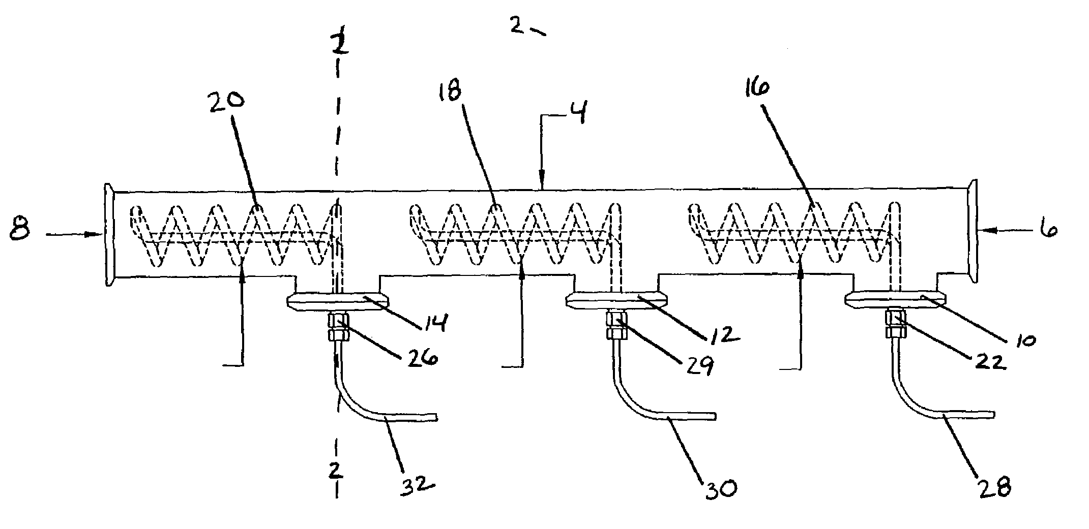
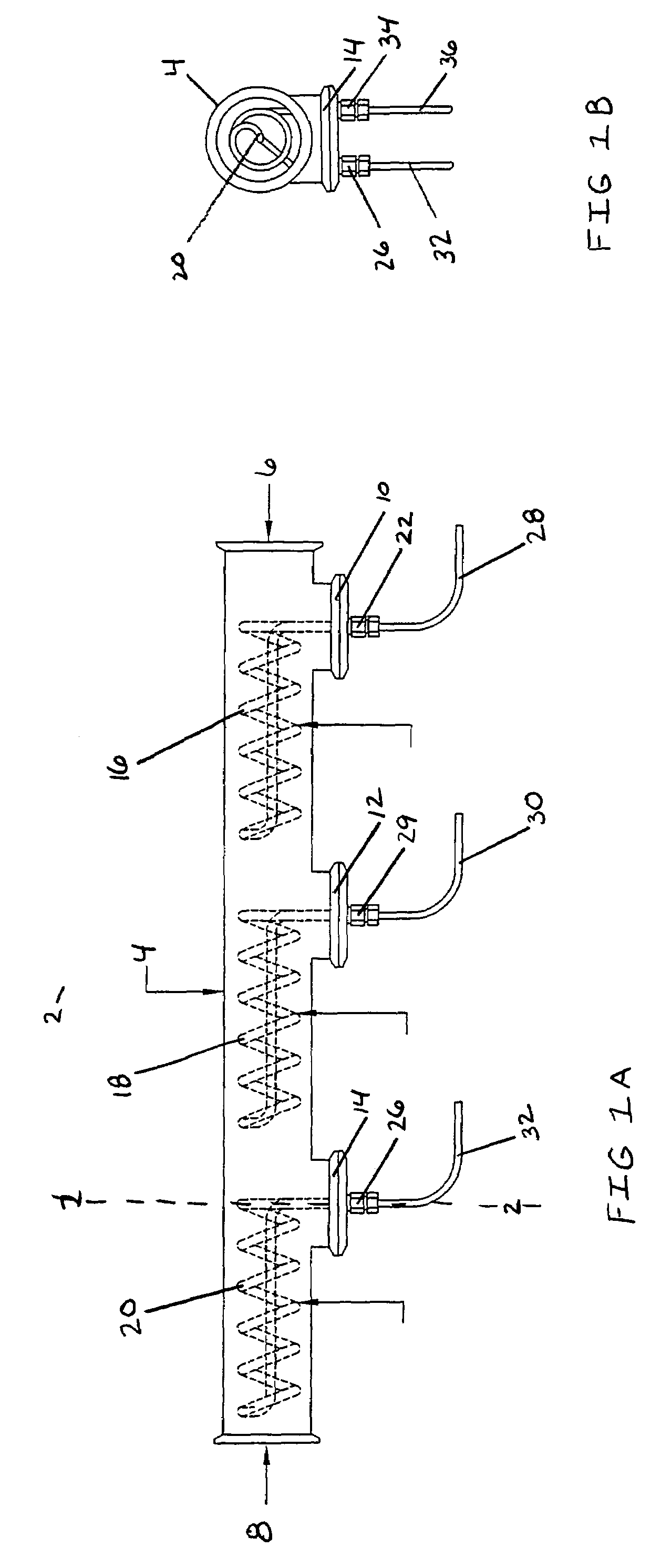
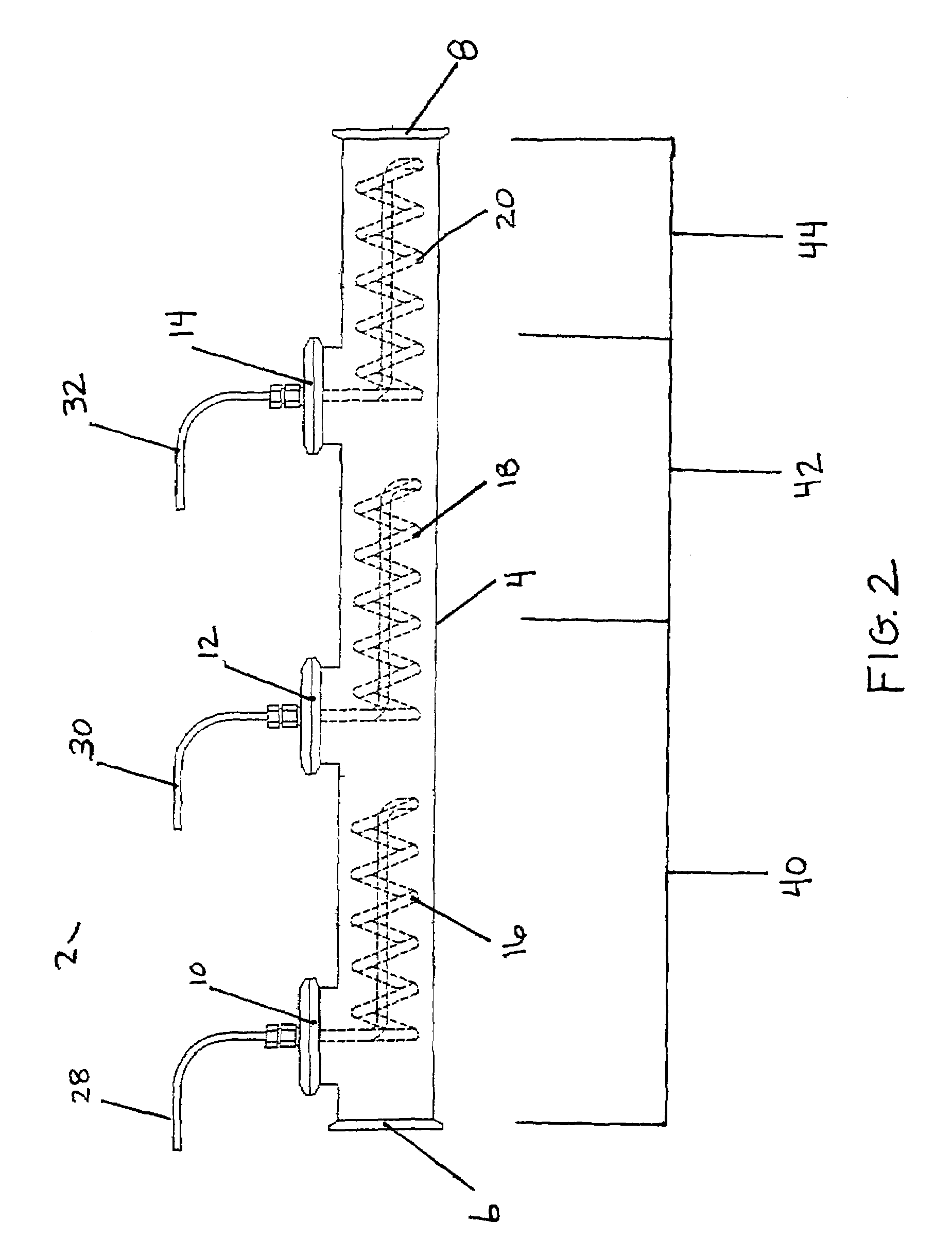
[0022]The present invention relates to a gaseous fluid generation system, a columnar heating device, and a method for generating a gaseous fluid. In one embodiment, the gaseous fluid generation system includes: (a) a reservoir-less columnar vessel having a liquid fluid inlet and a gaseous fluid outlet, oriented such that the gaseous fluid outlet is elevated with respect to the liquid fluid inlet; and (b) at least one resistive heating element contained within the columnar vessel.

[0023]FIG. 1A illustrates an example of a columnar heating device suitable for use in the present gaseous fluid generation system. Columnar heating device 2 includes reservoir-less columnar vessel 4 having liquid fluid inlet 6; gaseous fluid outlet 8; ports 10, 12, and 14; and resistive heating elements 16, 18, and 20. Reservoir-less columnar vessel 4 can be made of any of a number of suitable materials known in the art such as stainless s...


PUM

PropertyMeasurementUnit
pressureaaaaaaaaaa
power densityaaaaaaaaaa
temperatureaaaaaaaaaa

Abstract

The present invention relates to a gaseous fluid generation system, a columnar heating device, and a method for generating a gaseous fluid. In one embodiment, the gaseous fluid generation system includes a reservoir-less columnar vessel having a liquid fluid inlet and a gaseous fluid outlet and at least one resistive heating element contained within the columnar vessel. The columnar vessel is oriented such that the gaseous fluid outlet is elevated with respect to the liquid fluid inlet. In one embodiment, the gaseous fluid generation system includes at least one resistive heating element having a power density selected to heat a fluid selected from the group consisting of a liquid fluid, a saturated gaseous fluid and a superheated gaseous fluid. In one particular embodiment, resistive heating elements of the columnar vessel have a power density selected to heat both a liquid fluid and a gaseous fluid.

Description

BACKGROUND OF THE INVENTION[0001]Typical existing electric powered steam generating systems and boilers heat water using electric resistance elements arranged inside a holding reservoir (e.g., a tank or pressure vessel). The reservoir contains water which usually is heated via submerged electric tubular heaters located in the reservoir. These heaters usually operate in a static environment by raising a controlled quantity of water to a prescribed temperature, then releasing that water as required in the form of saturated steam. When steam is required in a typical existing steam generator, water moves from the holding reservoir through a throttle valve, converting the liquid into a saturated steam.[0002]The reservoir typically has a high and low level switch to control water height in the reservoir which introduces ambient temperature water to the reservoir as necessary. When mixed with the water already in the reservoir, this water can lower the temperature of the reservoir water to...

Claims


Application Information

Patent Timeline
Patent Type & Authority Patents(United States)
IPC IPC(8): F24H1/20F17C9/04F22B1/28F22B27/14
CPCF22B1/282F22B27/14F22B1/288
Inventor EVANS, ROBERT
Owner BETADYNE IND INC
Why Eureka
Try Eureka