MRI biopsy apparatus incorporating an imageable penetrating portion

Inactive Publication Date: 2007-07-19
DEVICOR MEDICAL PROD
View PDF95 Cites 227 Cited by
  • Summary
  • Abstract
  • Description
  • Claims
  • Application Information

AI Technical Summary

Problems solved by technology

Compatibility with such an environment requires that the instrument must be essentially non-ferromagnetic, so that it is not attracted by the magnetic field, which would pose a safety problem.
This consideration applies to any object that is used near or that is inserted into or implanted within the patient being imaged, because the magnetic field subjects such an object or implants, if ferro-magnetic, to undesirable forces and torques.

Method used


Image

  • MRI biopsy apparatus incorporating an imageable penetrating portion
  • MRI biopsy apparatus incorporating an imageable penetrating portion
  • MRI biopsy apparatus incorporating an imageable penetrating portion

Examples


Embodiment Construction

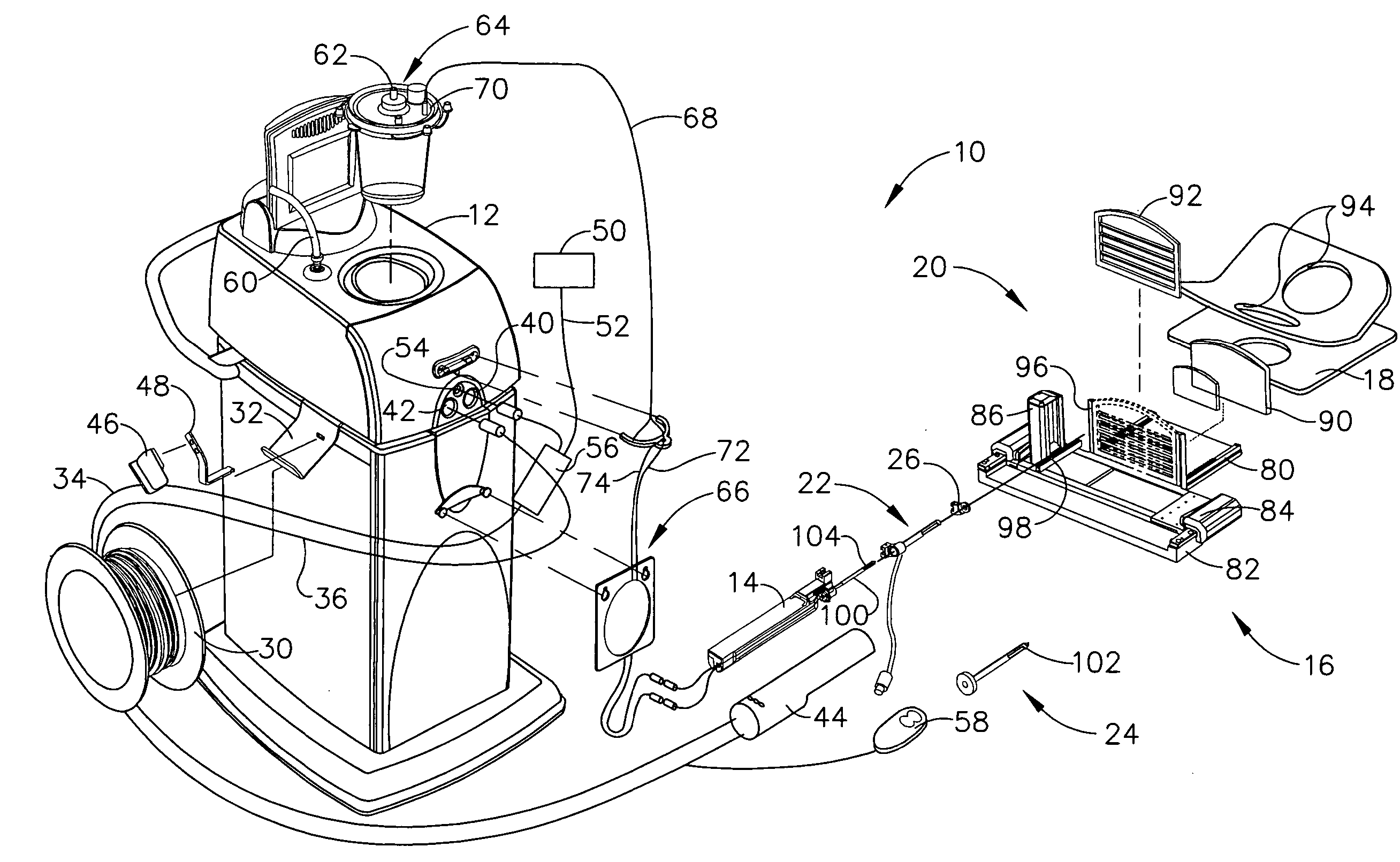
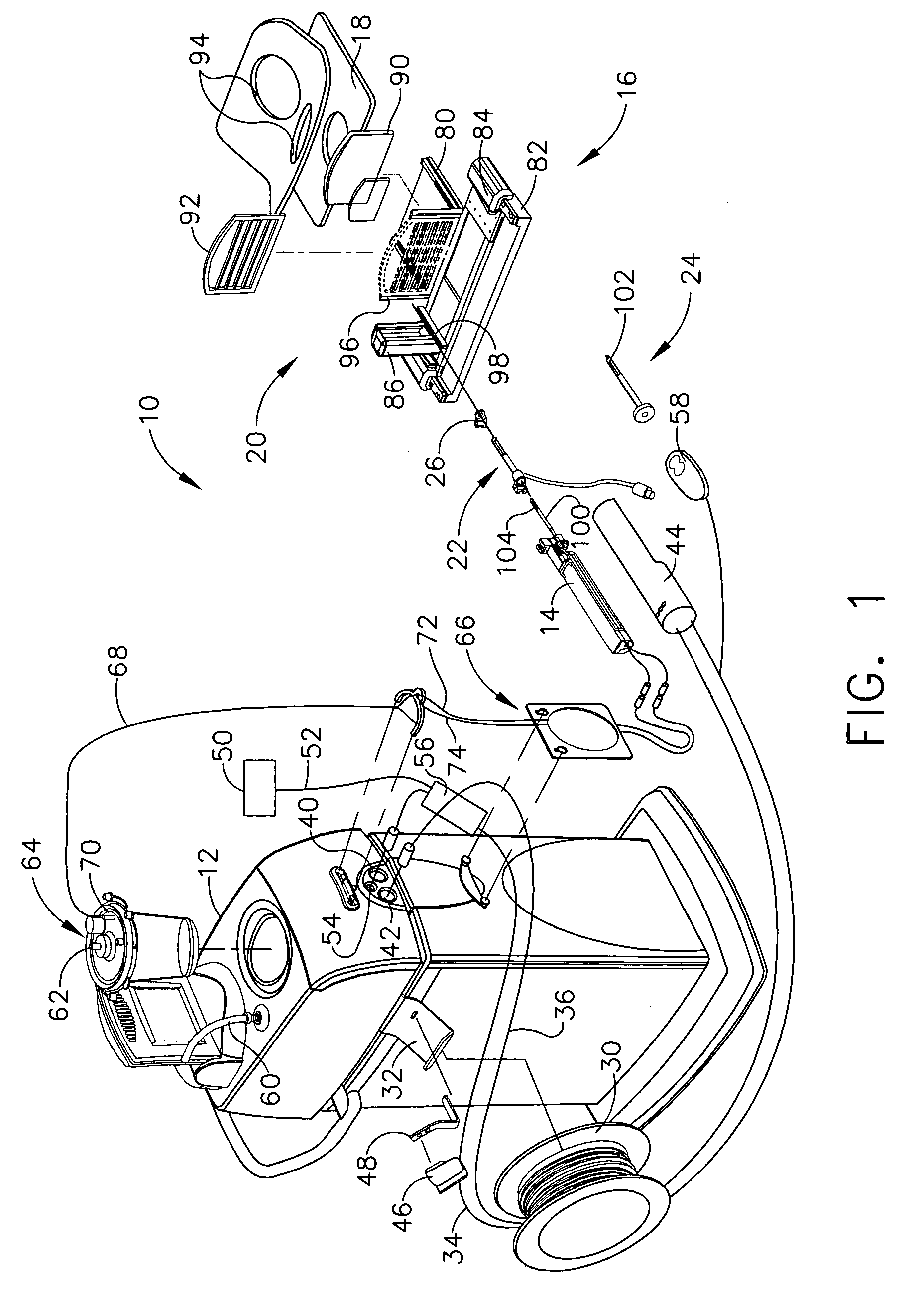
[0097] Turning to the Drawings, wherein like numerals denote like components throughout the several views, in FIG. 1, a Magnetic Resonance Imaging (MRI) compatible biopsy system 10 includes a guide that guides a sleeve and introducer obturator that are separate from the biopsy device itself and advantageously incorporate an improved piercing portion, MRI imageable features, and fluid handling capabilities. Mounting provisions allow for precise penetration along a desired trajectory without overshooting.

[0098] The MRI compatible biopsy system 10 includes a control module 12 that typically is placed outside of a shielded room containing an MRI machine (not shown) or at least spaced away to mitigate detrimental interaction with its strong magnetic field and / or sensitive radio frequency (RF) signal detection antennas. The control module 12 controls and powers an MRI biopsy device 14 that is compatible for use in close proximity to the MRI machine. An example of an MRI biopsy device 14 ...


PUM


Abstract

An obturator as part of a biopsy system enhances use with Magnetic Resonance Imaging (MRI) by indicating location of a side aperture in an encompassing cannula. The cannula (e.g., detached probe, sleeve sized to receive a core biopsy probe) includes a side aperture for taking a tissue sample. When the obturator is inserted in lieu of the biopsy device into the cannula, a notch formed in a shaft of the obturator corresponds to the side aperture. A dugout trough into the notch may further accept aqueous material to further accentuate the side aperture. In addition, a series of dimensionally varied apertures (e.g., wells, slats) that communicate through a lateral surface of the shaft and that are proximal to the side aperture receive an aqueous material to accentuate visibility in an MRI image, even in a skewed MRI slice through the cannula/obturator.

Description

CROSS REFERENCE TO RELATED APPLICATIONS [0001] The present application claims the benefit of PCT International Patent Appl. No. WO 2005 / 017775 of the same title filed 20 May 2005, which in turn claimed the benefit of U.S. Provisional Patent Appl. entitled “MRI BIOPSY DEVICE” to Hughes et al., Ser. No. 60 / 573,510, filed on 21 May 2004, the disclosures of which are hereby incorporated by reference in their entirety. [0002] The present application also claims the benefit of three U.S. nonprovisional patent applications entitled “MRI BIOPSY DEVICE” to Hughes et al., Ser. No. 11 / 076,612, filed on 10 Mar. 2005; “MRI BIOPSY DEVICE LOCALIZATION FIXTURE” to Hughes et al., Ser. No. 11 / 103,959, filed on 12 Apr. 2005; and “MRI BIOPSY APPARATUS INCORPORATING A SLEEVE AND MULTI-FUNCTION OBTURATOR” to Tsonton et al., Ser. No. 11 / 103,718, filed on 12 Apr. 2005, the disclosure of all three of which are hereby incorporated by reference in their entirety.FIELD OF THE INVENTION [0003] The present inven...

Claims


Application Information

Patent Timeline
Patent Type & Authority Applications(United States)
IPC IPC(8): A61B5/05
CPCA61B10/0275A61B19/201G01R33/286A61B2019/5408A61B2019/5454A61B2019/5236A61B90/11A61B2090/374A61B2090/3908A61B2090/3954A61B10/0041A61B2010/045A61B5/05A61B2090/3983A61B5/055
Inventor DIETZ, TIMOTHY G.DATTA, KESHAVAHIBNER, JOHN A.MURRAY, MICHAEL A.HUGHES, ROBERT
Owner DEVICOR MEDICAL PROD
Why Eureka
Try Eureka