Drip emitter

a technology of drip emitter and emitter body, which is applied in the direction of mechanical equipment, process and machine control, instruments, etc., can solve the problems of not easy to vandalize the subsurface emitter, the emitter is located above ground, and may be undesirable at parks and school grounds

Active Publication Date: 2007-08-23
RAIN BIRD CORP
View PDF85 Cites 73 Cited by
  • Summary
  • Abstract
  • Description
  • Claims
  • Application Information

AI Technical Summary

Problems solved by technology

Drip emitters located above ground, on the other hand, may be undesirable at parks and school grounds during daytime hours when children or other individuals are present.
Third, subsurface emitters are not easily vandalized, given their installation in a relatively inaccessible location, i.e., underground.
Such fluctuations result in the inefficient and wasteful use of water.
There is also a need in the irrigation industry to keep subsurface drip emitters from becoming obstructed, which results in insufficient water distribution and potential plant death.
Obstruction of an emitter may result from the introduction of grit, debris, or other particulate matter, both from debri...

Method used


Image

  • Drip emitter
  • Drip emitter
  • Drip emitter

Examples


Embodiment Construction

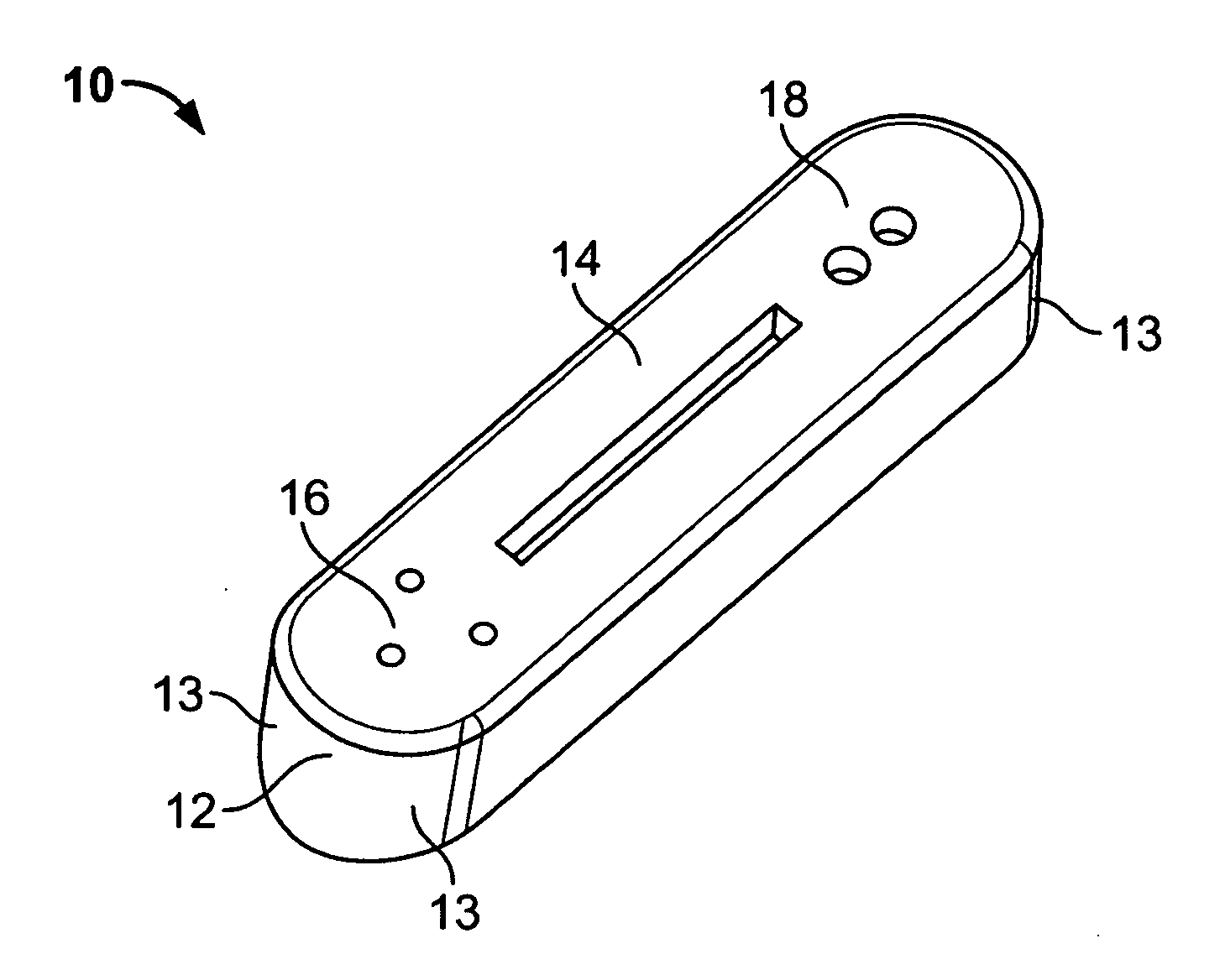
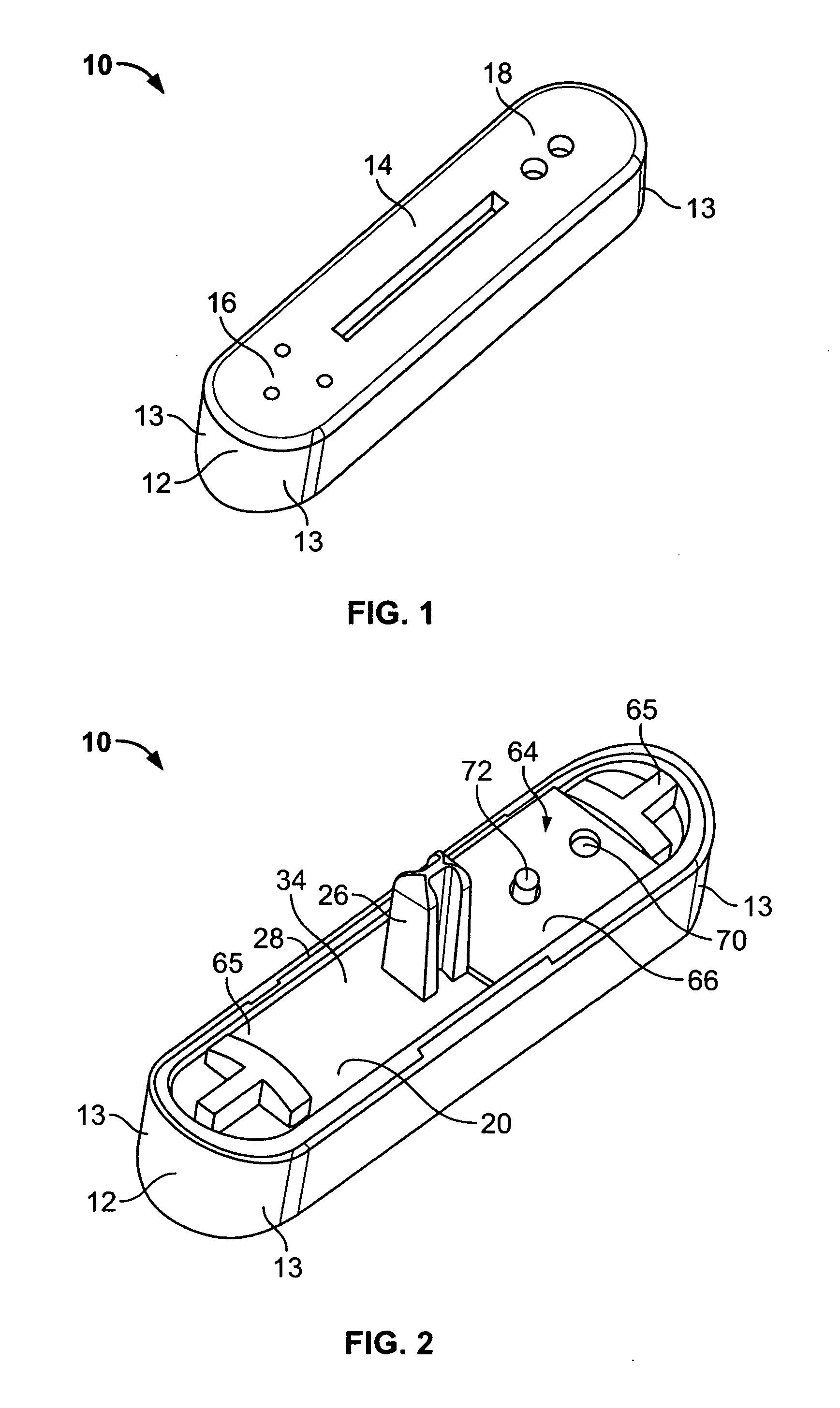
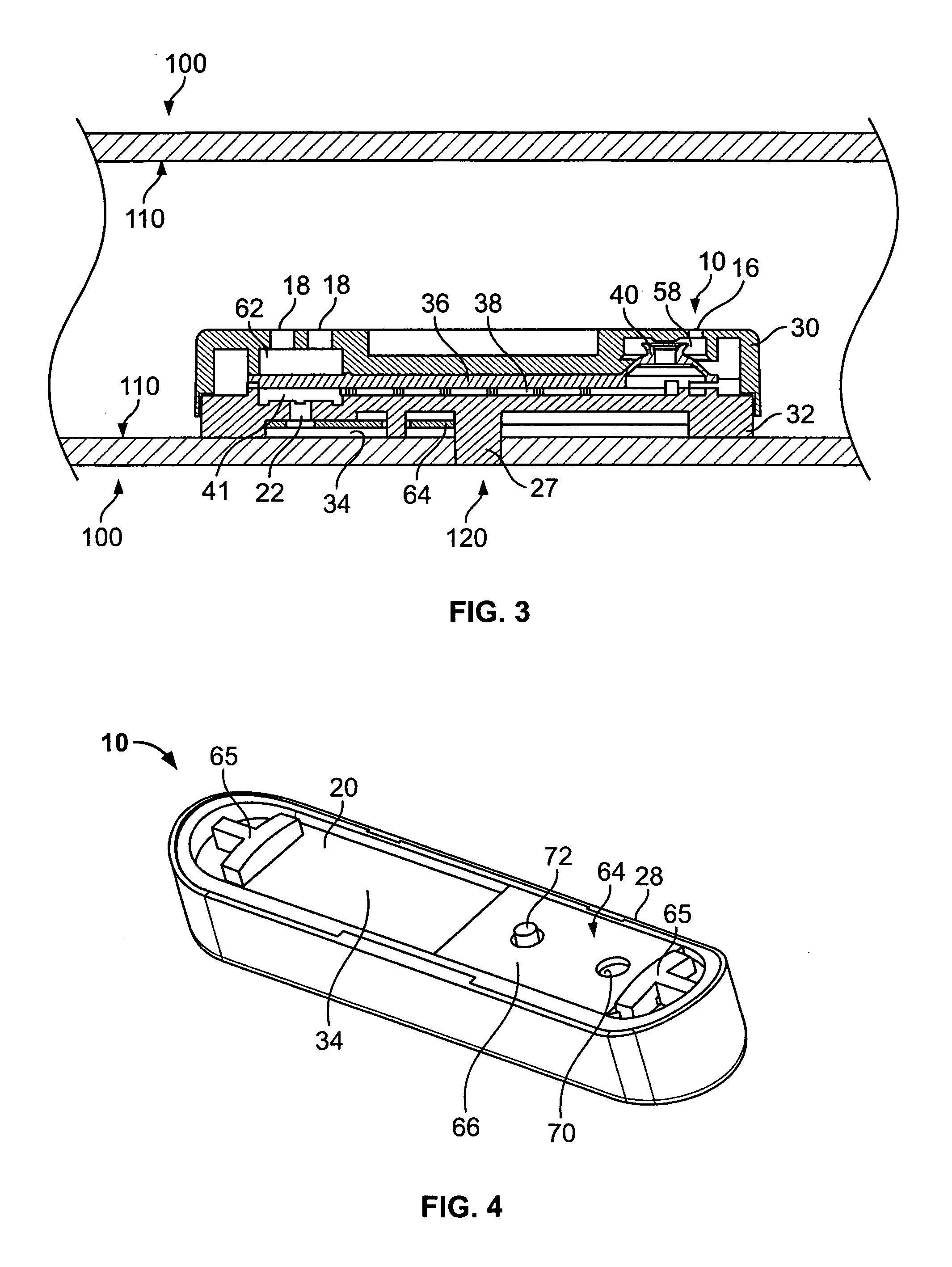
[0029] With respect to FIGS. 1-5, a drip irrigation emitter 10 is provided for delivering irrigation water from a water supply conduit, such as an irrigation supply tube, at a low volume, substantially trickle, or drip flow rate. The emitter 10 operates generally through the use of a tortuous path flow channel 38 that causes a pressure reduction between the irrigation tube and an emitter outlet 22. The emitter 10 includes a first inlet 16 for tapping a portion of the water flow from the irrigation tube, and, when the water pressure is above a predetermined minimum level, directing the flow to and through the tortuous path flow channel 38 for subsequent discharge to a desired location. In the preferred embodiment, the emitter 10 also includes a second inlet 18 for maintaining relatively constant output water flow by compensating for fluctuations in water pressure in the irrigation tube.

[0030] The emitter 10 comprises a compact housing 12 made of a sturdy and non-corrosive material. ...


PUM

PropertyMeasurementUnit
Pressureaaaaaaaaaa
Flow rateaaaaaaaaaa
Areaaaaaaaaaaa

Abstract

A drip emitter is provided for delivering irrigation water from a supply tube to an emitter outlet at a reduced and relatively constant flow rate. Water enters the emitter through a first inlet and proceeds into a first chamber. When the water pressure is above a predetermined level, a one-directional valve opens to allow fluid flow past the first chamber, through a tortuous path flow channel, and through an emitter outlet. A second inlet is used to compensate for water pressure fluctuations in the supply tube to maintain output flow at a relatively constant rate. Water enters the second inlet and presses a flexible diaphragm toward a water metering surface to provide pressure-dependent control of the output flow. A copper member is mounted to the emitter over the emitter outlet to prevent plant root intrusion into the emitter outlet.

Description

FIELD OF THE INVENTION [0001] The present invention relates to irrigation drip emitters, and more particularly, to subsurface irrigation drip emitters. BACKGROUND OF THE INVENTION [0002] Drip irrigation emitters are generally known in the art for use in delivering irrigation water to a precise point at a predetermined and relatively low volume flow rate, thereby conserving water. Such irrigation devices typically comprise an emitter housing connected to a water supply tube through which irrigation water is supplied under pressure. The drip irrigation device taps a portion of the relatively high pressure irrigation water from the supply tube for flow through a typically long or small cross section flow path to achieve a desired pressure drop prior to discharge at a target trickle or drip flow rate. In a conventional system, a large number of the drip irrigation devices are mounted at selected positions along the length of the supply tube to deliver the irrigation water to a large num...

Claims


Application Information

Patent Timeline
IPC IPC(8): B05B15/00B05B1/30
CPCA01G25/023Y10T29/49826A01G25/06
Inventor MAVRAKIS, RICKPOPE, BRIANSHAH, SAMIRO'NEAL, CHRISTOPHER LELANDLEYBOURN, DAVID
Owner RAIN BIRD CORP
Why Eureka
Try Eureka