Method and Apparatus for Producing Direct Reduced Iron

a technology of direct reduction and iron, applied in the direction of manufacturing converters, blast furnace details, furnaces, etc., can solve the problems of reducing the operational savings in electrical energy and upkeep, and the suggestion of using ejectors has not proved practical, so as to achieve significant savings in capital and operational expenses, less expensive equipment, and less electrical energy

Active Publication Date: 2007-10-25
HYL TECH SA DE CV
View PDF16 Cites 27 Cited by
  • Summary
  • Abstract
  • Description
  • Claims
  • Application Information

AI Technical Summary

Benefits of technology

[0017] It is therefore an object of the present invention to provide a process and apparatus for the direct reduction of iron ores with important savings in capital and operational expenses over existing processes and apparatus for the production of DRI.
[0018] It is another object of the present invention to provide a process and apparatus for the direct reduction of iron ores that requires less expensive equipment and less electrical energy than other similar processes now in operation.

Problems solved by technology

For the nearly fifty years of commercial production DRI, the reducing and cooling gases have been recirculated by means of large and expensive compressors.
As discussed in greater detail below, savings in the millions of dollars in reduced large initial capital costs and as well as greatly reduced operational savings in electrical energy and upkeep result.
Even the suggested use of ejectors apparently has not proven practical (for recycling reducing gas).

Method used


Image

  • Method and Apparatus for Producing Direct Reduced Iron
  • Method and Apparatus for Producing Direct Reduced Iron
  • Method and Apparatus for Producing Direct Reduced Iron

Examples


example 1

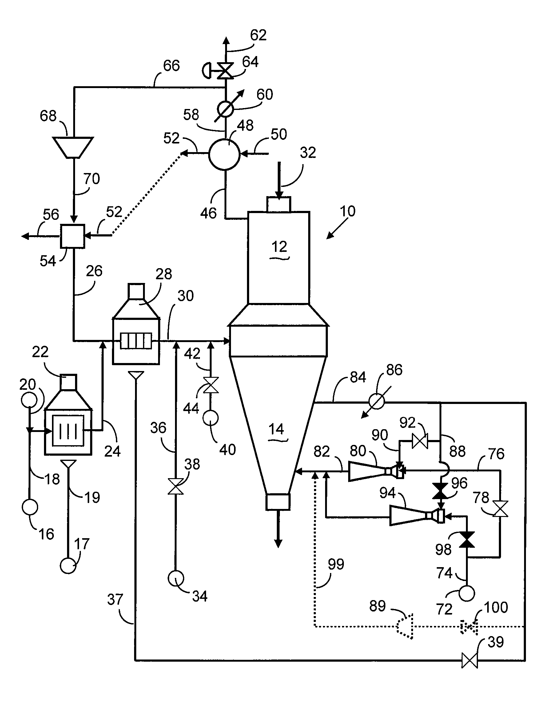
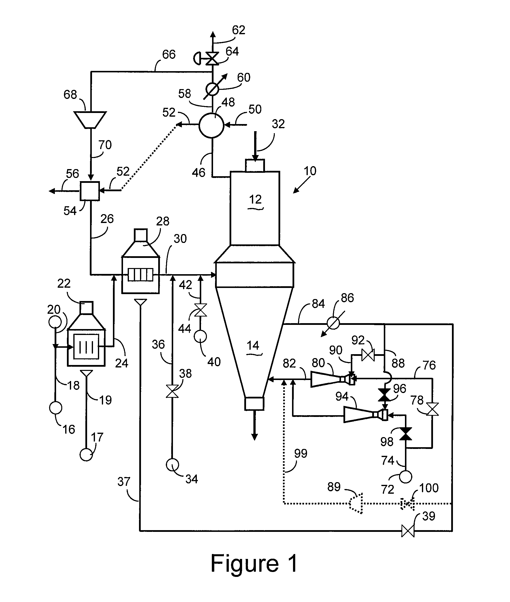
[0045] The cooling gas compressor in a direct reduction plant with the embodiment of the process shown in FIG. 1 was substituted by an ejector utilizing as motive gas a stream of natural gas fed at a pressure of 12 kg / cm2 absolute and at temperature of 25° C. The flow rate of natural gas fed to the ejector was 175 NCMH per metric Ton of Fe produced. The composition of natural gas was: 1.6% H2; 1.1% CO2; 93.3% CH4; 0.5%N2; 2.7% C2H6; and 0.8% C3H8. The flow rate of recycle cooling gas entering the ejector was 301 NCMH per metric ton of Fe produced at a pressure of 4.65 kg / cm2 absolute and with a composition as follows: 9.266% H2; 0.129% CO; 0.207% CO2; 89.089% CH4; 0.474% N2; and 0.836% H2O.

[0046] A stream of cooling gas, effluent from the ejector at a pressure of 5.25 kg / cm2 absolute, entered the cooling zone at a flow rate of 476 NCMH per ton of Fe produced, at a temperature of 27° C. and having the following composition: 6.448% H2; 0.082% CO; 0.535% CO2; 90.637% CH4; 0.484% N2; 0...


PUM

PropertyMeasurementUnit
temperatureaaaaaaaaaa

Abstract

A direct reduction process for producing direct reduced iron (DRI) in a reduction reactor having a reduction zone for reducing iron-oxides-containing particles, such as iron ore pellets, to DRI by reaction of said iron oxides with a high temperature reducing gas, and a cooling zone for lowering the temperature of the DRI produced in said reduction zone, wherein a stream of cooling gas, usually natural gas, is circulated through said cooling zone, a portion of said cooling gas is withdrawn from the cooling zone, cooled and cleaned in a gas cooler and a portion of the cooled gas is recycled to said reduction zone by means of an ejector utilizing the high-pressure natural gas make-up feed as the ejector's motive fluid. Using an ejector for recycling the cooling gas instead of using a mechanical compressor provides significant savings in electricity and in capital, operational and maintenance costs. A direct reduction plant having a DRI cooling zone which uses at least one ejector in recycling at least a portion of cooling gas to the cooling zone.

Description

FIELD OF THE INVENTION [0001] The present invention relates to processes for the direct reduction of iron oxide particles to still solid particles containing mainly metallic iron by the use of recirculated and regenerated hot reducing gases. Most typically, the hot reduced particles are cooled with a recirculating cooling gas with natural gas added as make up to the cooling gas. BACKGROUND OF THE INVENTION [0002] The present invention is thus directed to the direct reduction of iron oxide particles to produce direct reduced iron (DRI), also known in the industry as sponge iron. More specifically, the present invention is directed to improvements in the methods and equipment employed for recycling cooling gas to the cooling zone of a direct reduction reactor. [0003] For the nearly fifty years of commercial production DRI, the reducing and cooling gases have been recirculated by means of large and expensive compressors. [0004] In the present invention, the normal compressor utilized f...

Claims


Application Information

Patent Timeline
Patent Type & Authority Applications(United States)
IPC IPC(8): C21B13/02C21C5/40
CPCC21B13/02C21B13/0086C21B13/029C21B2100/22C21B2100/44Y02P10/122Y02P10/134Y02P10/143
Inventor ZENDEJAS-MARTINEZ, EUGENIO
Owner HYL TECH SA DE CV
Why Eureka
Try Eureka