Backlight device and method for controlling light source brightness thereof

a backlight device and light source technology, applied in the field of controlling light sources, can solve the problem of not being able to make the backlight device to generate the desired luminous effect, and achieve the effect of reducing the cost of the backlight devi

Inactive Publication Date: 2007-11-08
IND TECH RES INST
View PDF7 Cites 37 Cited by
  • Summary
  • Abstract
  • Description
  • Claims
  • Application Information

AI Technical Summary

Benefits of technology

[0017]As the base frequency of the PWM signal is directly controlled in the present invention, processes of analog-t

Problems solved by technology

However, the property of LEDs varies along with temperature and service life, such that the driving current desig

Method used


Image

  • Backlight device and method for controlling light source brightness thereof
  • Backlight device and method for controlling light source brightness thereof
  • Backlight device and method for controlling light source brightness thereof

Examples


Embodiment Construction

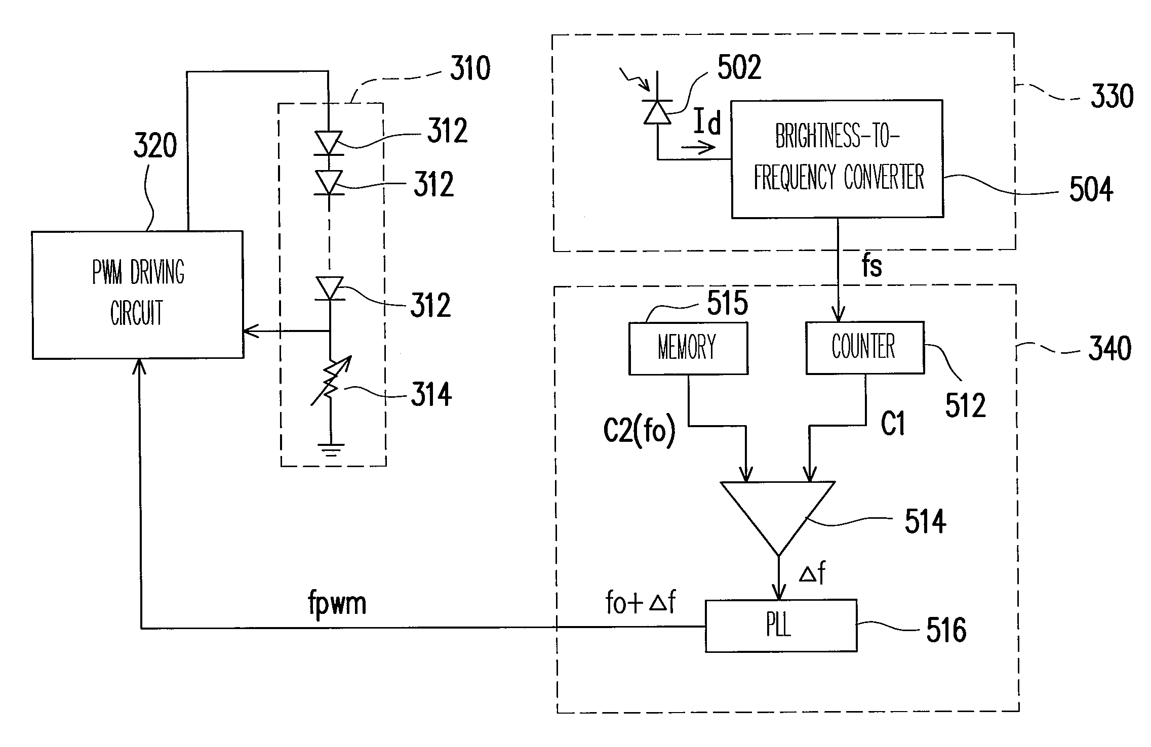
[0028]FIG. 3 is a circuit block diagram of the backlight device according to a preferred embodiment of the present invention. Referring to FIG. 3, a backlight device 300 provided by the present invention comprises a light source module 310 having a plurality of light sources 312, a PWM driving circuit 320, a detecting circuit 330, and a control unit 340.

[0029]FIG. 4 is a flow chart of the method for controlling the light source brightness according to a preferred embodiment of the present invention. Referring to FIGS. 3 and 4 together, in Step S401, the PWM driving circuit 320 generates a PWM signal to drive the light sources 312 in the light source module 310 to illuminate. In other preferred embodiments, the light sources 312 can be LEDs of different colors, such as red, blue, and green LEDs.

[0030]When the light source module 310 is driven, the detecting circuit 330 detects the luminous brightness of the light source module 310 as described in Step S403, and the detected brightnes...


PUM


Abstract

A backlight device includes a light source module having a plurality of light sources, a detecting circuit, a control unit, and a pulse width modulation (PWM) driving circuit. The detecting circuit is used for detecting the brightness of the light source module and generating a detecting signal to the control unit, such that the control unit outputs a control signal according to the detecting signal. In addition, the PWM driving circuit is used for generating a PWM signal for driving the light source module. In the present invention, the PWM driving circuit adjusts the base frequency of the PWM signal according to the control signal without adjusting the duty cycle of the PWM signal, so as to control the brightness of the light sources.

Description

CROSS-REFERENCE TO RELATED APPLICATION[0001]This application claims the priority benefit of Taiwan application serial no. 95116005, filed on May 5, 2006. All disclosure of the Taiwan application is incorporated herein by reference.BACKGROUND OF THE INVENTION[0002]1. Field of Invention[0003]The present invention relates to a method for controlling light source. More particularly, the present invention relates to a method for controlling the light source brightness of a backlight device.[0004]2. Description of Related Art[0005]Before being dispatched from the factory, light-emitting diode (LED) backlight devices should be adjusted to the optimum by the manufacturer. However, the property of LEDs varies along with temperature and service life, such that the driving current designed by the manufacturer for driving the LED cannot make the backlight device to generate desired luminous effect. Therefore, many patents directed to solve the above problem are issued, such as US Patent Publica...

Claims


Application Information

Patent Timeline
IPC IPC(8): G09G3/32
CPCG09G3/3406G09G2360/145G09G2320/0633
Inventor HUANG, LI-RENLIN, CHUNG-WEIYEH, CHIN-CHING
Owner IND TECH RES INST
Why Eureka
Try Eureka