LED Lighting Lamp Tube

a technology of led lighting and lamp tubes, which is applied in the direction of non-electric lighting, semiconductor devices of light sources, lighting and heating apparatus, etc., can solve the problems of limiting light output, and achieve the effects of saving power, high lumen output, and long li

Inactive Publication Date: 2008-02-14
CHAN KK
View PDF6 Cites 100 Cited by
  • Summary
  • Abstract
  • Description
  • Claims
  • Application Information

AI Technical Summary

Benefits of technology

[0004] It is, therefore, an objective to provide a lighting lamp tube, which uses LEDs as its lighting source in order to provide a high lumen output, long life time, power saving light

Problems solved by technology

Moreover, the ends of tube can turn black afte

Method used


Image

  • LED Lighting Lamp Tube
  • LED Lighting Lamp Tube
  • LED Lighting Lamp Tube

Examples


Embodiment Construction

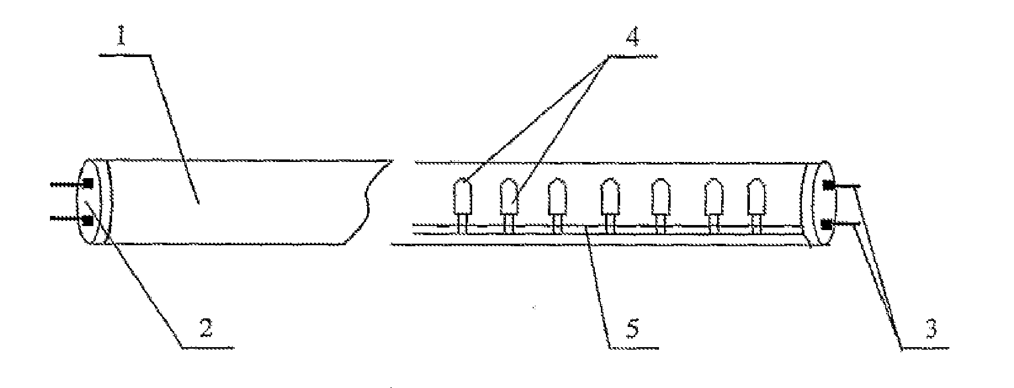
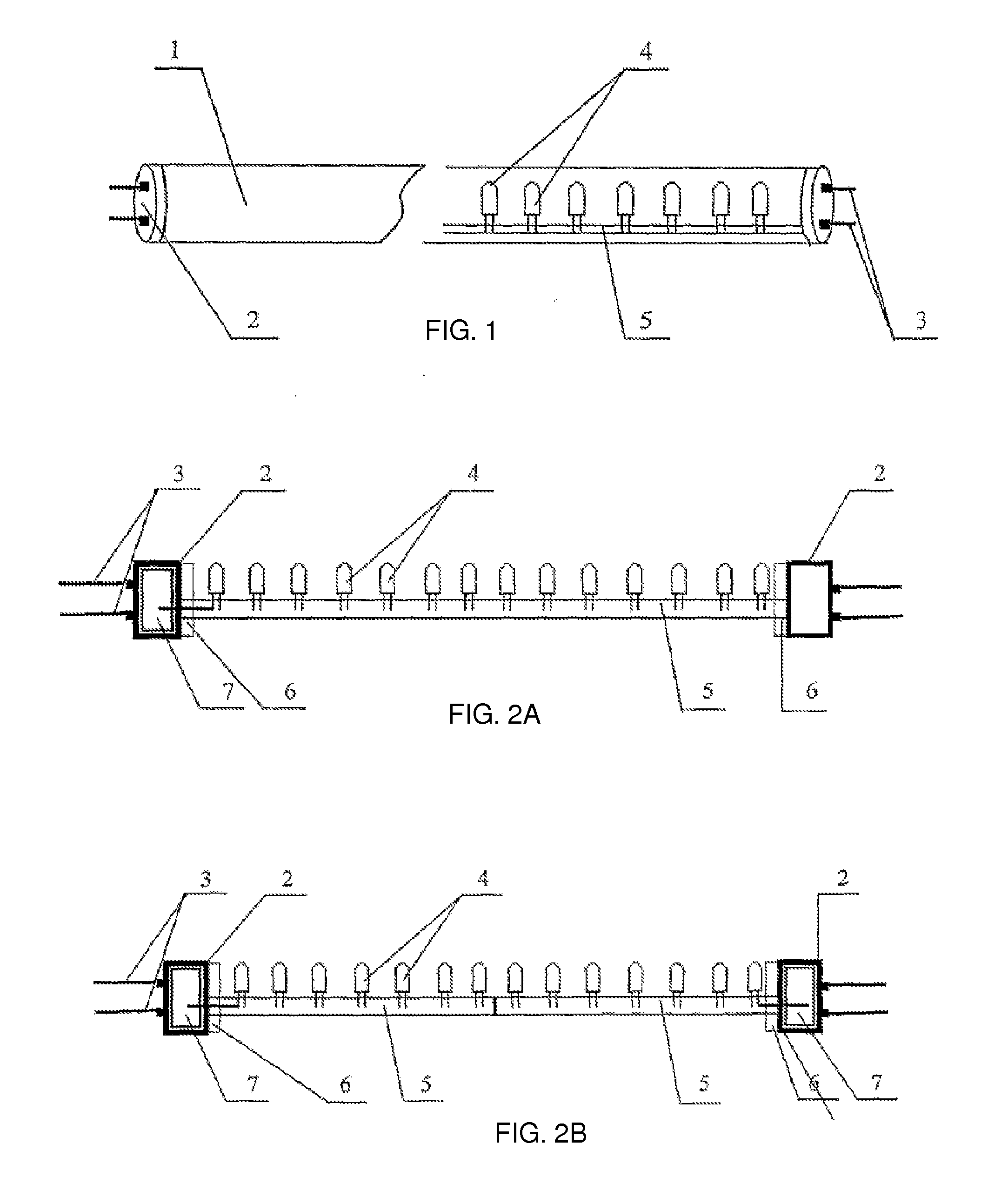
[0021] As shown in FIGS. 1 and 2, the LED lighting lamp tube comprises a transparent tube body (1), lamp caps (2), electrode pins (3), pedestals (6) mounted at the connection position of the transparent tube body (1) and the lamp caps (2), a power supply converter (7) located adjacent to the lamp caps (2) and inside the tube body (1), a PCB (5) and a plurality of LEDs (4) mounted on the PCB (5). The number of LEDs (4) is depended on needed brightness, for example, the brightness of a 100 Watt generic lamp tube will need 120 LED, with a 7-8 Watt of power consumption. A particular light color can be achieved by colored LEDs (4) in the transparent tube.

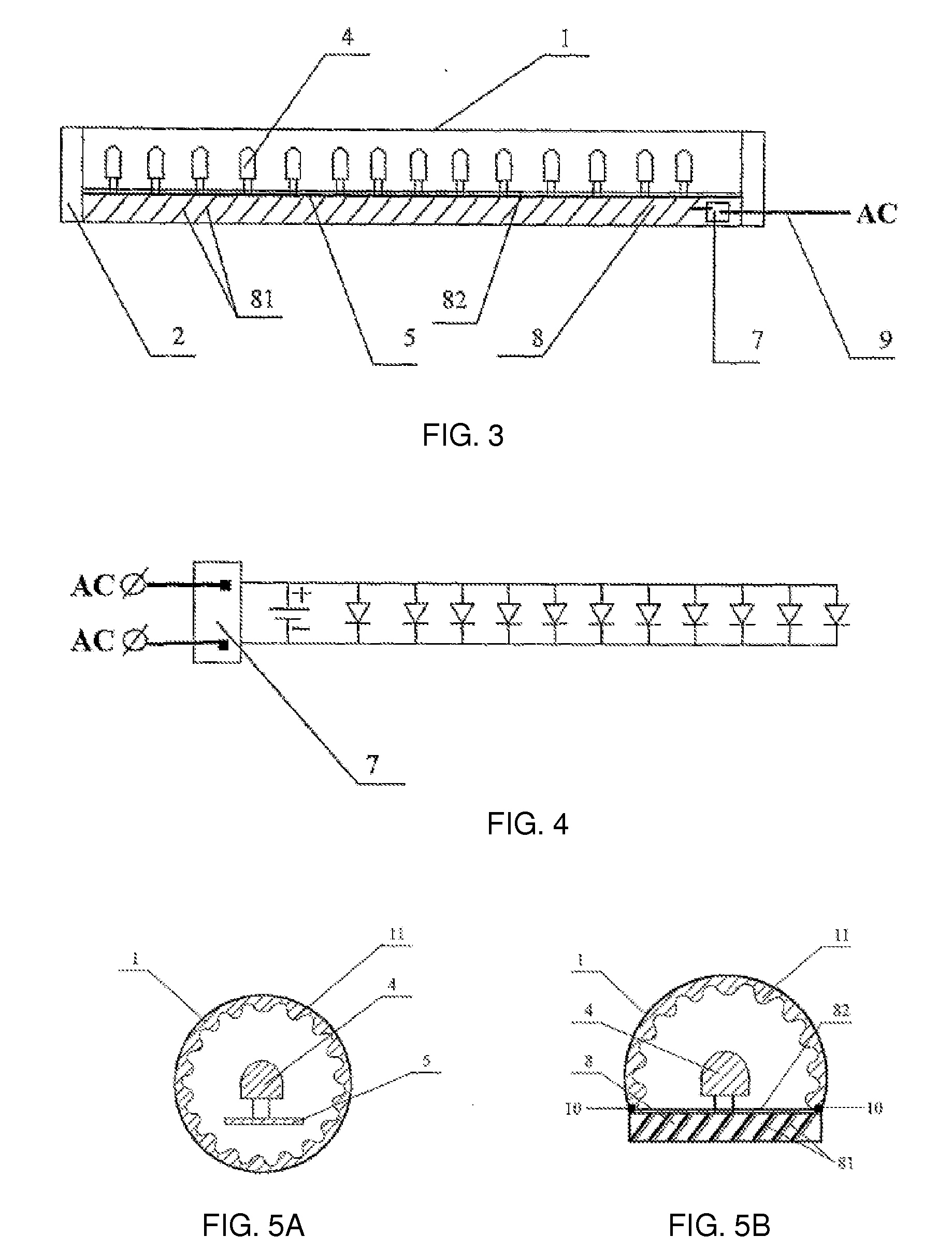
[0022] As shown in FIGS. 2A and 4, the power supply converter (7) is installed adjacent to one of the lamp caps (2) inside the tube (1). The input of converter (7) is connected with electrode pins (3) and the electricity will go to the LED (4) power supply circuit after conversion to direct current. The LEDs (4) emit light to illuminate...


PUM


Abstract

A LED lighting lamp tube comprises a transparent tube body, lamp caps, electrode pins, pedestals mounted at the connection position of the transparent tube body and the lamp caps, a power supply converter located adjacent to the lamp caps and inside the tube body, a PCB and a plurality of LED mounted on the PCB. These LED are connected in parallel or in series, and a light-scattering plate may be disposed over these LED. A plurality of LED chips can be directly mounted on the light-scattering plate. The lamp caps and the electrode pins possess the same international standards as common lamp tubes.

Description

CROSS REFERENCE TO RELATED APPLICATIONS [0001] This application is a continuation of international patent application PCT / CN2006 / 000241 filed on Feb. 21, 2006, and claims priority to Chinese patent application 200520002000.1 filed on Feb. 21, 2005, which are incorporated by reference herein.TECHNICAL FIELD [0002] This invention relates to a light emitting diode (LED) lighting lamp tube and more particularly to a lamp tube which uses LEDs as its lighting source and which can replace generic fluorescent lamp tubes. BACKGROUND ART [0003] A daylight or fluorescent lamp tube typically uses a filament or collided argon ionization as a heater, vaporizing the mercury to emit strong ultraviolet rays, and emitting white light through fluorescence powder inside the tube. The present fluorescent lamp tubes can have certain shortcomings such as a short life time, easily broken filaments, flickering light that causes eye strain and some ultraviolet radiation. Moreover, the ends of tube can turn b...

Claims


Application Information

Patent Timeline
IPC IPC(8): F21S4/00F21V29/00
CPCF21Y2101/02F21Y2103/003F21W2121/00F21V23/004F21K9/175F21V23/006F21K9/278F21Y2103/10F21Y2115/10
Inventor CHAN, SZE KEUN
Owner CHAN KK
Why Eureka
Try Eureka