Helical structure and method for plasma lamp

a plasma lamp and helical structure technology, applied in the field of lighting techniques, can solve the problems of electrodeless lamps that still have many limitations, electrodeless lamps consume much energy, and have a high initial cost, so as to improve the heat transfer of electrodeless plasma lamps, improve manufacturability and design flexibility, and improve the effect of heat transfer characteristics

Inactive Publication Date: 2013-09-03
TOPANGA USA
View PDF4 Cites 3 Cited by
  • Summary
  • Abstract
  • Description
  • Claims
  • Application Information

AI Technical Summary

Benefits of technology

[0009]In a specific embodiment, the present invention provides a plasma lamp apparatus. The apparatus includes a post structure comprising a material overlying a surface region of the post structure, which has a first end and a second end. The apparatus also has a helical coil structure operably configured along one or more portions of the post structure according to a specific embodiment. In a preferred embodiment, the helical coil acts as an inductive coupling structure and also facilitates thermal energy transport. The apparatus has a bulb device configured to the first end of the post structure, which is coupled to the helical coil structure. In a preferred embodiment, the bulb device comprises a gas filled vessel that is filled with an inert gas such as Argon and a fluorophor or light emitter such as Mercury, Sodium, Dysprosium, Sulfur or a metal halide salt such as Indium Bromide, Scandium Bromide, or Cesium Iodide (or it can simultaneously contain multiple fluorophors or light emitters). The gas filled vessel can also include a metal halide, or other metal pieces that will discharge electromagnetic radiation according to a specific embodiment. The device has a resonator coupling element configured to feed radio frequency energy to at least the helical coil structure and to cause the bulb device to emit electromagnetic radiation. In a specific embodiment, the radio frequency energy has a frequency ranging from 1000 MHz to less than about 8 MHz, but can be others. As used herein, the terms “first” and “second” are not intended to imply order and should be interpreted by ordinary meaning. Additionally, such terms may be defined by at least the descriptions provided in the specification as well as by meanings consistent with one of ordinary skill in the art.
[0010]In an alternate embodiment of the present invention, a method for lowering the resonant frequency and improving the heat transfer characteristics of the device is created. The method includes creating a helical shaped RF output coupling-element that is either wrapped around a dielectric material, or simply coiled through air. The presence of a dielectric medium within the helical shaped RF output coupling-element serves to more efficiently absorb thermal energy that is generated by the bulb and subsequently transferred through the RF output coupling-element and the dielectric material. In creating a helical shaped RF output coupling element, the inductance of the resonant structure is increased leading to lower resonant frequencies at which the device operates at without substantially changing the size of the resonant structure. In lowering the operational resonant frequency, amplifiers with higher efficiencies can be used to operate the lamp. Alternatively the lower frequency resonator can be used to couple RF energy to larger bulbs and in conjunction with higher power amplifiers, higher lumens output lamps can be realized. Adding a dielectric material within the helical shaped RF output coupling element, helps in transferring the heat from the bulb to the resonator / lamp body.
[0012]Moreover, the present invention provides an alternative plasma lamp apparatus. The apparatus has a support structure having a first end and a second end and a coil structure configured along one or more portions of the support structure according to a specific embodiment. The apparatus also has a bulb device configured to the first end of the support structure according to a specific embodiment. The apparatus has a ground potential coupled to the second end of the support structure and a coupling element configured to feed at least radio frequency energy to at least the coil structure and to cause the bulb device to emit electromagnetic radiation. Still further, the present invention provides a method of improving heat transfer of an electrode-less plasma lamp according to an alternative embodiment. The method includes using a helical shaped element to draw thermal energy from a plasma lamp to a thermal sink region in a specific embodiment.
[0013]Benefits are achieved over pre-existing techniques using the present invention. In a specific embodiment, the present invention provides a method and device having configurations of input, output, and feedback coupling elements that provide for electromagnetic coupling to the bulb whose power transfer and frequency resonance characteristics that are largely independent of the conventional dielectric resonator, but can also be dependent upon conventional designs. In a preferred embodiment, the present invention provides a method and configurations with an arrangement that provides for improved manufacturability as well as design flexibility. Other embodiments may include integrated assemblies of the output coupling element and bulb that function in a complementary manner with the present coupling element configurations and related methods for street lighting applications. Still further, the present method and device provide for improved heat transfer characteristics, as well as further simplifying manufacturing and / or retrofitting of existing and new street lighting, such as lamps, and the like. In a specific embodiment, the present method and resulting structure are relatively simple and cost effective to manufacture for commercial applications. In a specific embodiment, the present invention includes a helical resonator structure, which increases inductance and therefore reduces the resonating frequency of a device. In a preferred embodiment, the resonating frequency may be about 250 MHz and less or about 100 MHz and less depending upon the type of coil, number of windings, and other parameters. In a specific embodiment, the present method and lamp device has a substantially exposed arc, in contrast to conventional plasma lamps where the arc of the bulb is substantially surrounded by the dielectric resonator / waveguide limiting the ability of the lamp to be used with typical luminaries. Depending upon the embodiment, one or more of these benefits may be achieved. These and other benefits may be described throughout the present specification and more particularly below.

Problems solved by technology

Although highly successful, the Edison bulb consumed much energy and was generally inefficient.
Fluorescent lighting is much more efficient than incandescent lighting, but often has a higher initial cost.
Although somewhat successful, the electrodeless lamp still had many limitations.
The dielectric material (such as Alumina) used for the dielectric resonator / waveguide must have low losses at RF frequencies resulting in higher material cost.
Furthermore, the dielectric resonator / waveguide is difficult to manufacture resulting in an expensive lamp.
As an example, electrodeless lamps have not been successfully deployed in high volume for general lighting applications.
Additionally, electrodeless lamps are generally difficult to disassemble and assembly leading to inefficient use of such lamps.

Method used


Image

  • Helical structure and method for plasma lamp
  • Helical structure and method for plasma lamp
  • Helical structure and method for plasma lamp

Examples


Embodiment Construction

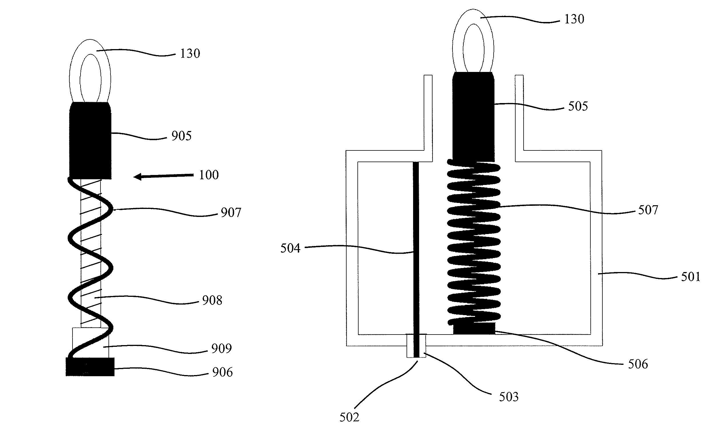
[0040]According to the present invention, techniques for lighting are provided. In particular, the present invention provides a method and device using a plasma lighting device having a shaped resonator assembly including a helical or coil structure, which is coupled to a radio frequency source. Merely by way of example, such plasma lamps can be applied to applications such as stadiums, security, parking lots, military and defense, streets, large and small buildings, vehicle headlamps, aircraft landing, bridges, warehouses, uv water treatment, agriculture, architectural lighting, stage lighting, medical illumination, microscopes, projectors and displays, any combination of these, and the like.

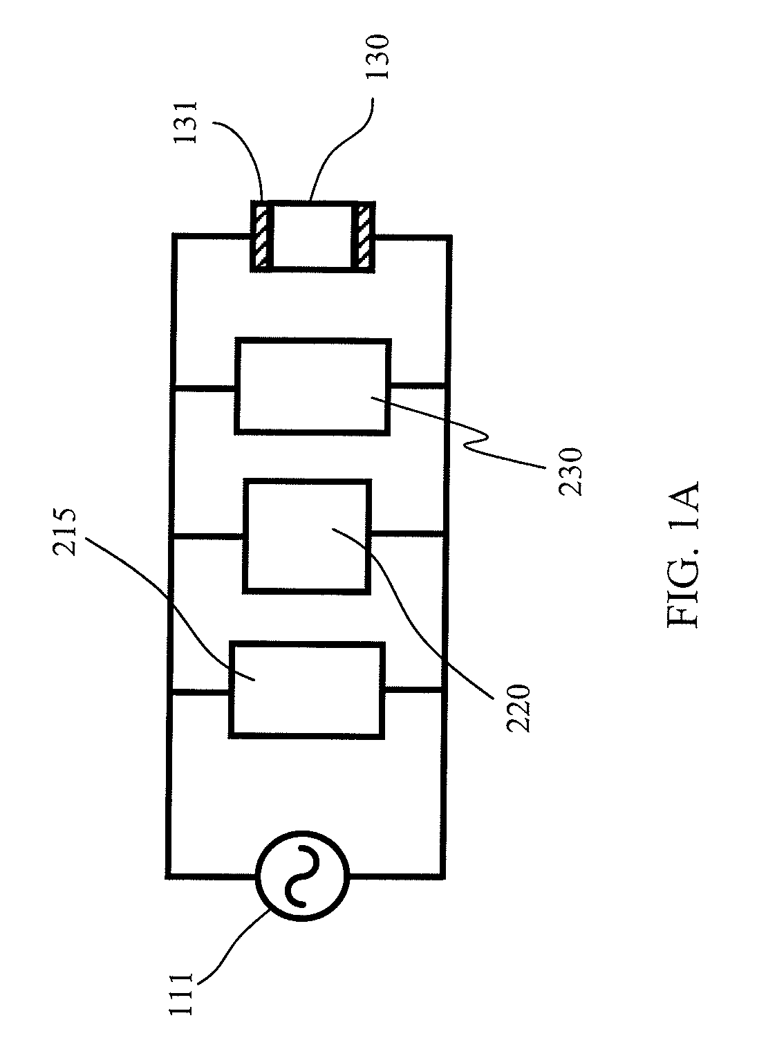
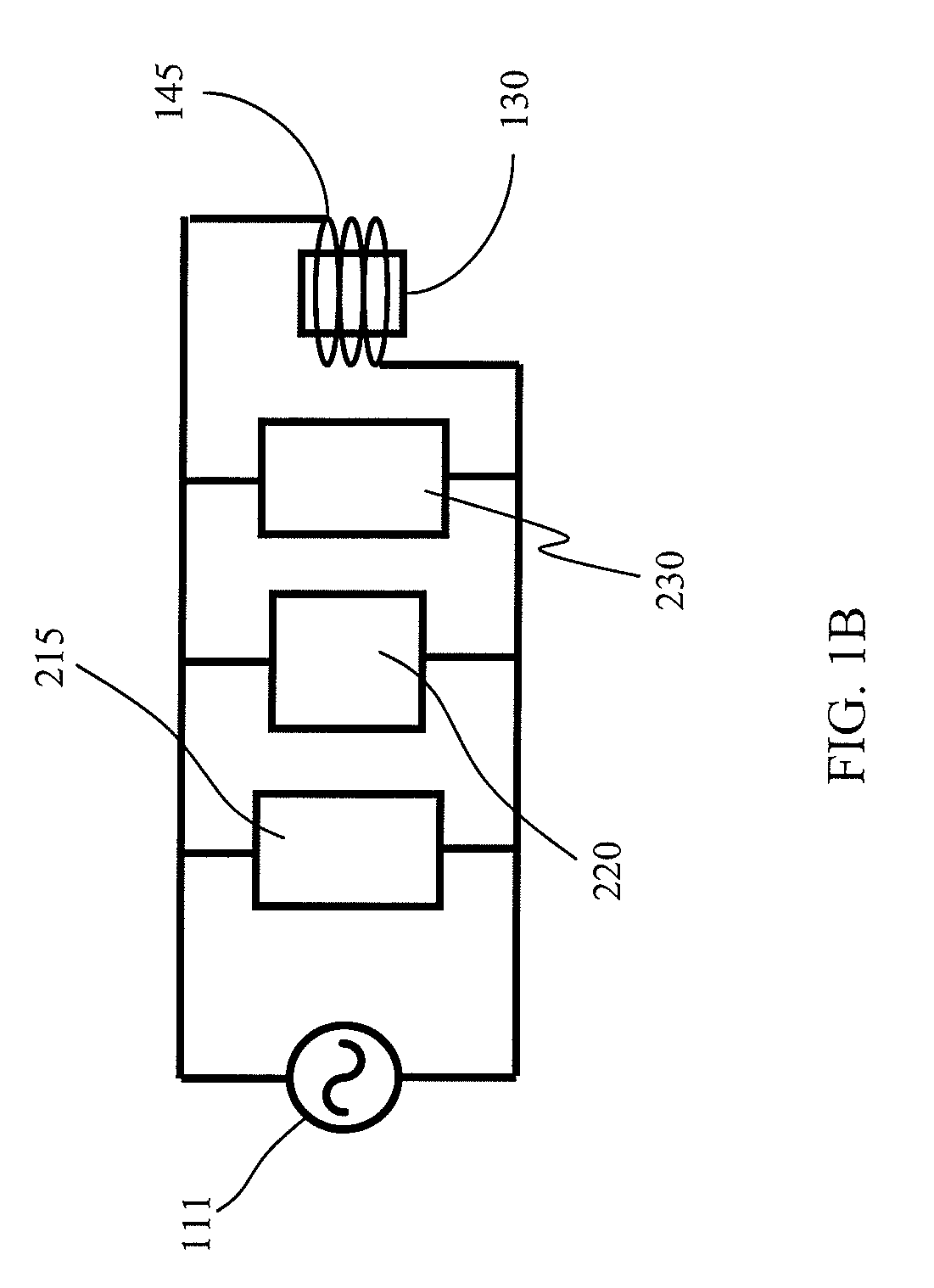
[0041]FIG. 1A illustrates a general schematic for efficient energy transfer from an RF source 111 to gas fill vessel 130. This diagram as well as all of the other diagrams are intended to be illustrative of one implementation, which should not unduly limit the scope of the claims herein. One of...


PUM


Abstract

A plasma lamp apparatus includes a post structure with a material overlying a surface region of the post structure, which has a first end and a second end. The apparatus also has a helical coil structure configured along the post structure. The apparatus includes a bulb with a fill material capable of emitting electromagnetic radiation. A resonator coupling element configured to feed radio frequency energy to at least the helical coil causes the bulb device to emit electromagnetic radiation.

Description

CROSS-REFERENCE TO RELATED APPLICATION[0001]This application claims priority from provisional patent application Ser. No. 61 / 185,556, filed Jun. 9, 2009, entitled Helical Structure and Method for Plasma Lamp, which is incorporated by reference herein for all purposes.BACKGROUND OF THE INVENTION[0002]This invention relates to lighting techniques. In particular, the invention provides a method and device using a plasma lighting device having a shaped resonator assembly including a helical or coil structure, which is coupled to a radio frequency source. Such plasma lamps can be applied to applications such as stadiums, security, parking lots, military and defense, streets, large and small buildings, vehicle headlamps, aircraft landing, bridges, warehouses, uv water treatment, agriculture, architectural lighting, stage lighting, medical illumination, microscopes, projectors and displays, and similar uses.[0003]From the early days, human beings have used a variety of techniques for light...

Claims


Application Information

Patent Timeline
Patent Type & Authority Patents(United States)
IPC IPC(8): H05B41/16
CPCH01J65/044F21V14/00
Inventor BROCKETT, TIMOTHY J.SCHMELZER, DAVID P.MATLOUBIAN, MEHRANESPIAU, FREDERICK M.
Owner TOPANGA USA
Why Eureka
Try Eureka