
Shark deterrent device
a shark and device technology, applied in the field of shark deterrent devices, can solve the problems of limited effectiveness, difficult to carry spear guns, and often not being allowed to use in ecologically fragile areas, and achieve the effect of convenient carrying and stowing, and easy extension
- Summary
- Abstract
- Description
- Claims
- Application Information
AI Technical Summary
Benefits of technology
Problems solved by technology
Method used
Image

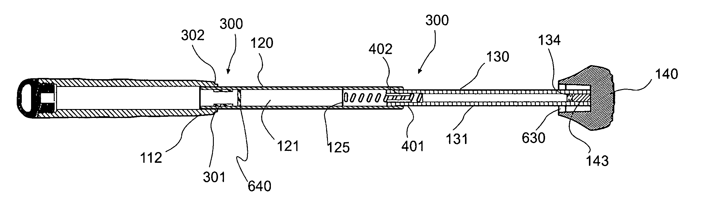
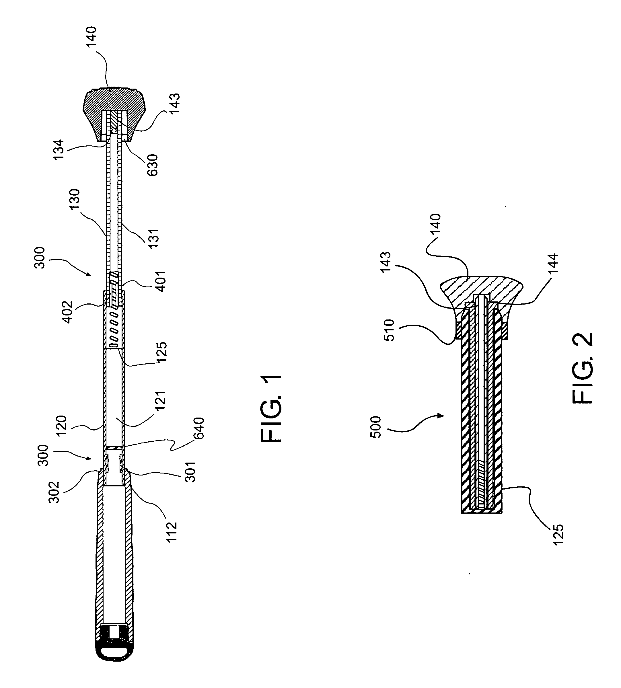
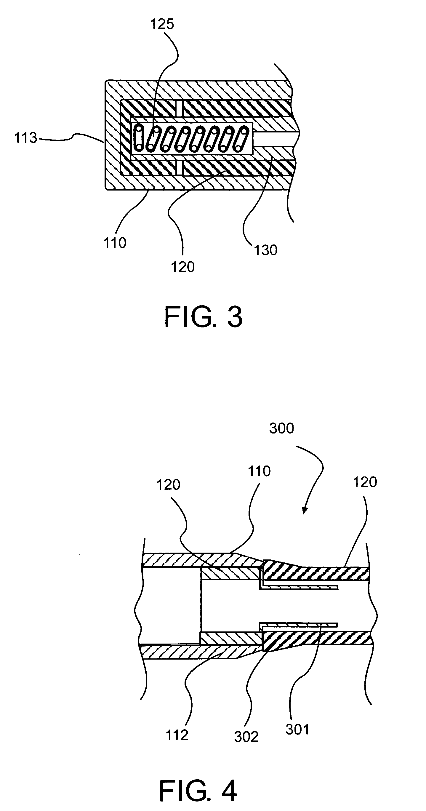
Examples
Embodiment Construction
[0025] Reference will now be made in detail to embodiments of the present invention, examples of which are illustrated in the accompanying drawings. As embodied herein, the present invention is a diver's utility tool, one embodiment of which is a shark deterrent device.
[0026] An embodiment of the present invention is shown in FIG. 1 as a shark deterrent device 10. The shark deterrent device comprises at least one shaft, and the shaft may be cylindrical. As shown in FIG. 1, one embodiment of device 10 comprises three cylindrical shafts, first hollow cylindrical shaft 110, second hollow cylindrical shaft 120, third hollow cylindrical shaft 130, and tip 140. Embodiments of the present invention may include, but are not limited to, one, two, or three or more cylindrical shafts. Discussion of a proximal end or portion indicates the end or portion closest to the operator, and discussion of a distal end or portion indicates the end or portion away from the operator.
[0027] With reference ...
PUM
 Abstract
Description
Claims
Application Information