

Image-capturing system and method
- Summary
- Abstract
- Description
- Claims
- Application Information
AI Technical Summary
Benefits of technology
Problems solved by technology
Method used
Image

Examples
Embodiment Construction
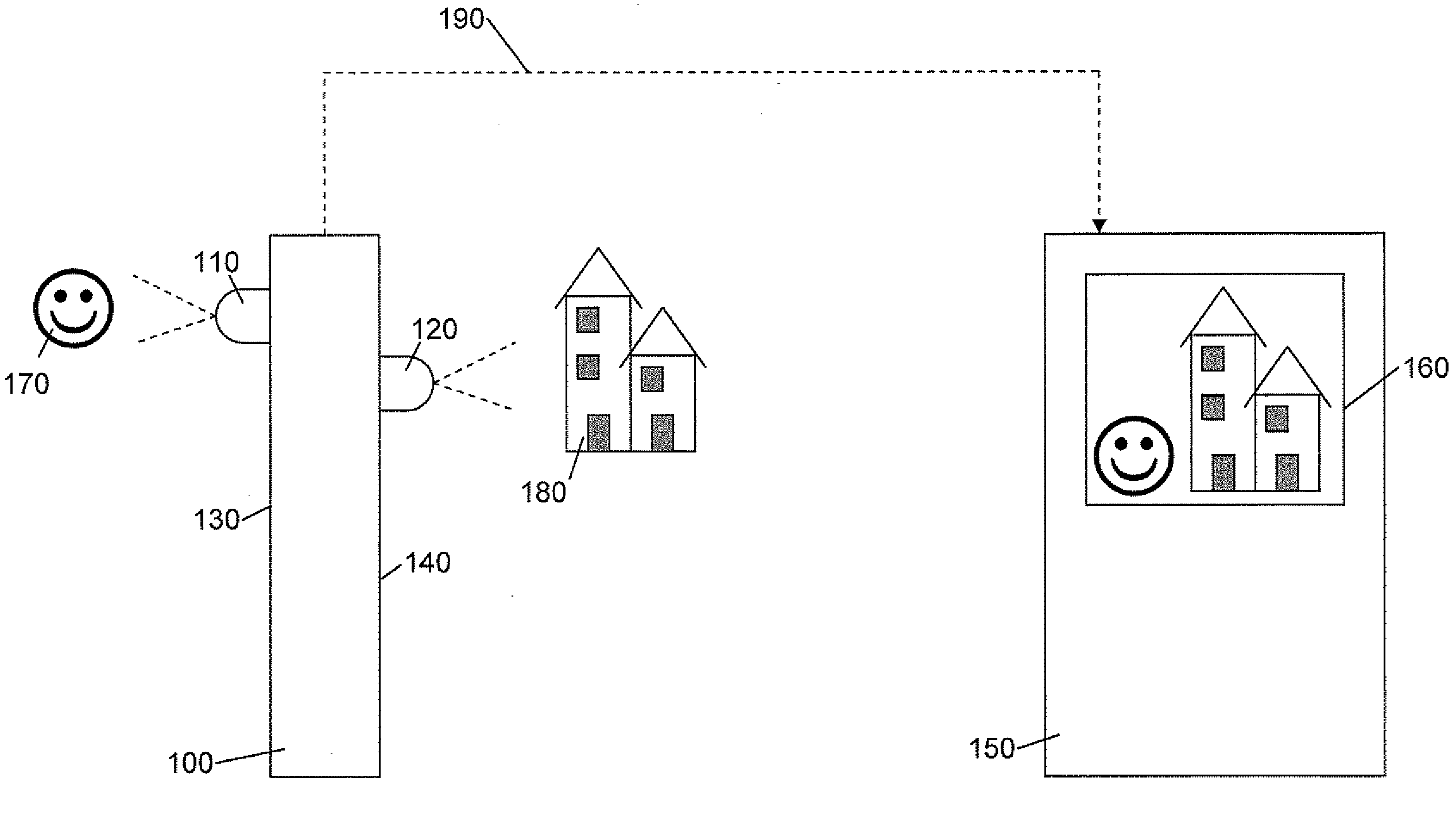
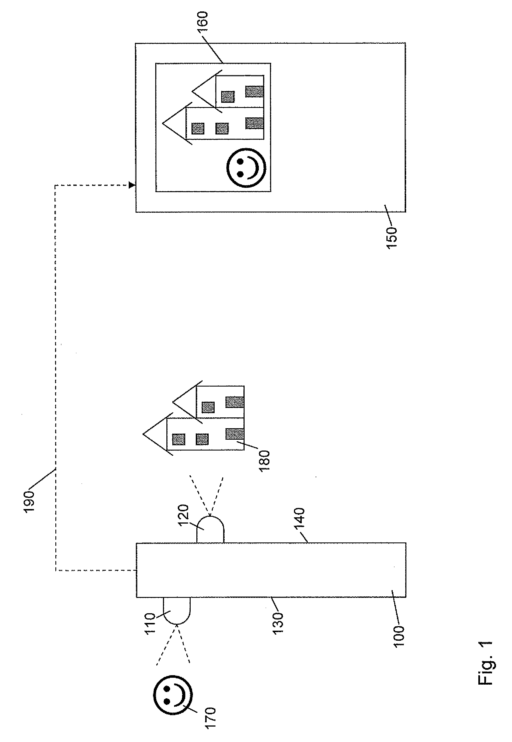
[0035]FIG. 1 depicts a profile of an electronic device 100. Electronic device 100 may be configured to connect to a displaying device 150 via a network. Electronic device 100 may include a first camera 110, and a second camera 120. Electronic device 100 may include a portable communication device, a mobile radio terminal, a Personal Digital Assistant (PDA), a mobile phone, or any other electronic device including two or more cameras.
[0036]First camera 110 and second camera 120 may be any kind of camera that is capable of capturing images digitally, i.e., converting light into electric charge and process it into electronic signals, so-called picture data. In this document, picture data captured from one picture is defined as one frame, which will be described more in detail further on. Such camera may be a video camera, a camera for still photography or an image sensor, such as Charge Coupled Device (CCD) and Complementary Metal Oxide Semiconductor (CMOS). First and second cameras 11...
PUM
 Abstract
Description
Claims
Application Information