Optical image-taking structure

An optical image and optical technology, applied in optics, optical components, image communication, etc., can solve problems such as image blur, achieve simple focusing, improve camera quality and functions, and achieve real-time and complete vibration compensation effects

Inactive Publication Date: 2008-06-25
ALTEK CORP
View PDF0 Cites 1 Cited by
  • Summary
  • Abstract
  • Description
  • Claims
  • Application Information

AI Technical Summary

Problems solved by technology

[0007] The technical problem to be solved by the present invention is to provide an optical imaging structure with vibration compensation and combi

Method used


Image

  • Optical image-taking structure
  • Optical image-taking structure
  • Optical image-taking structure

Examples


Example Embodiment

[0027] In order to have a further understanding of the purpose, structure, features, and functions of the present invention, the following detailed descriptions are provided in conjunction with the embodiments.
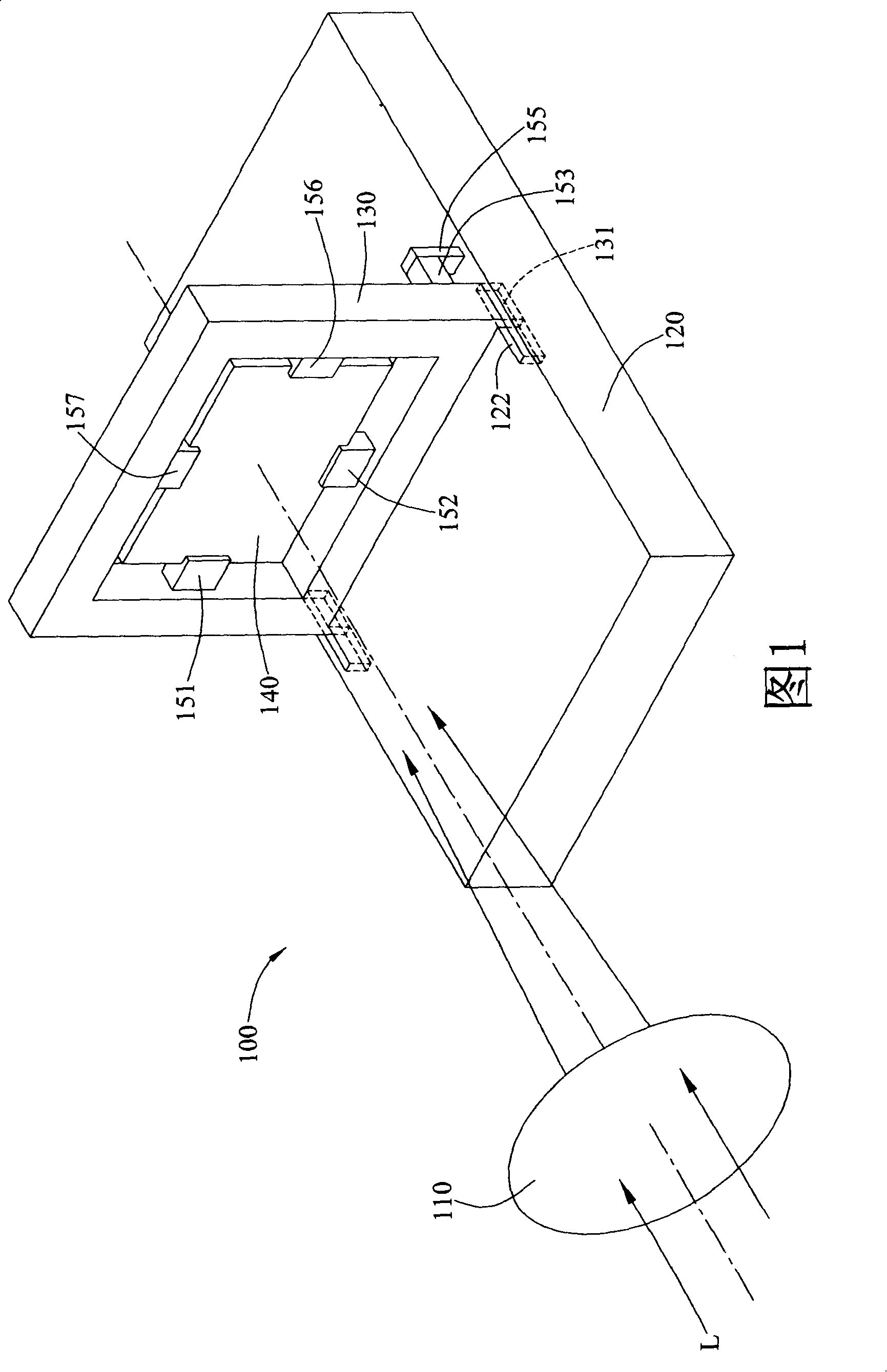
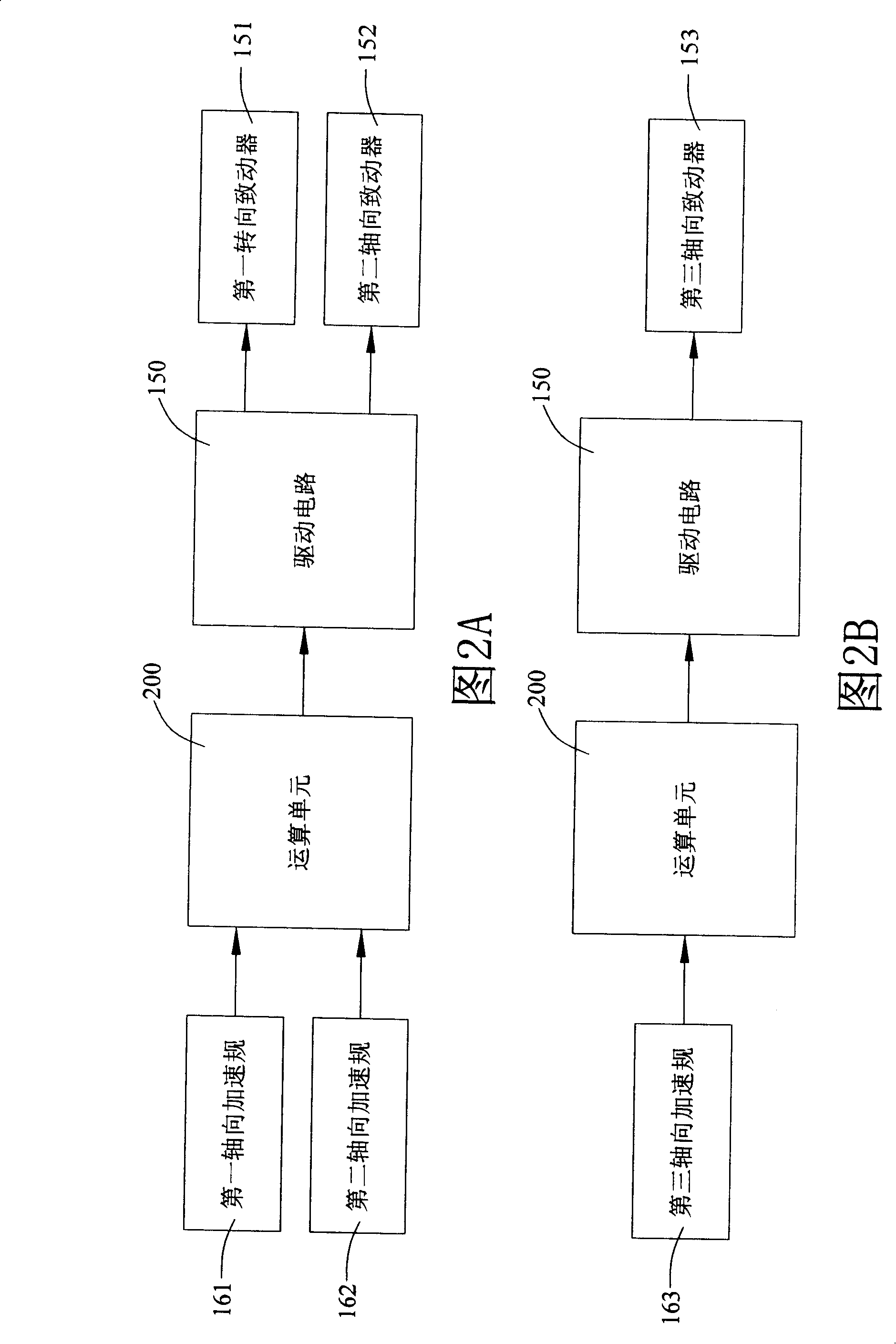
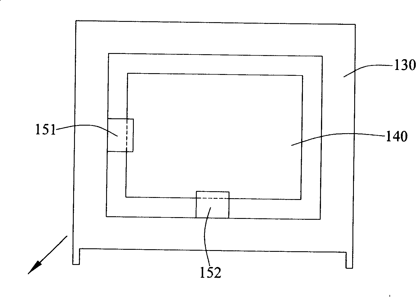
[0028] First, referring to FIG. 1, it is a side perspective view of the best embodiment of the optical imaging structure of the present invention. The optical imaging structure 100 of the present invention has a lens group 110, a substrate 120, a frame 130, a photosensitive element 140, a first axial actuator 151, a second axial actuator 152, and a first axis. Three-axis actuator 153.

[0029] The lens group 110 includes at least one convex lens for imaging the incident light L at a predetermined position. The substrate 120 is spaced apart from the lens group 110 and a sliding groove 122 and a fixing post 155 are respectively formed on two opposite sides of the substrate 120. The frame 130 is vertically arranged on the substrate 120, and an embedding portion 131 is respec...


PUM


Abstract

The present invention discloses an optical image capturing structure, comprising a basal plate, a framework, a photosensitive element, a first axial actuator, a second axial actuator and a third axial actuator. The framework relatively moves on the basal plate, while the photosensitive element is arranged inside the framework to capture an optical image; the first axial actuator is connected between the framework and the photosensitive element; the second axial actuator is connected between the framework and the photosensitive element; the third axial actuator is connected between the framework and the basal plate; the first axial actuator, the second axial actuator and the third axial actuator are used to move the photosensitive element in a first axial direction, a second axial direction and a third axial direction, thereby ensuring that the photosensitive element follows optical axis change to shift, and ensuring that the optical image is clearly imaged on the photosensitive element.

Description

technical field [0001] The present invention relates to an optical imaging structure, in particular to an optical imaging structure capable of providing vibration compensation function and fast focusing function. Background technique [0002] With the development of technology and image transmission technology, existing portable optical imaging equipment (such as camera phones, digital cameras, personal digital assistants, tablet computers and digital cameras, etc.) increasingly favored by consumers. And it is widely used by general consumers as an auxiliary tool for daily image recording. [0003] While consumers demand miniaturization, thinner, and lower prices for optical imaging equipment, they also put forward higher requirements for the quality of the captured object images, that is, the captured object images are required to be clear. . [0004] Optical imaging equipment generally sets up a set of autofocus lens groups on the optical imaging equipment, such as an a...

Claims


Application Information

Patent Timeline
IPC IPC(8): G03B13/36G03B5/00G02B7/09H04N5/225
Inventor 黄旭炼
Owner ALTEK CORP
Why Eureka
Try Eureka