This helps you quickly interpret patents by identifying the three key elements:
Problems solved by technology
Method used
Benefits of technology
[0012]An engine may include: a main drive shaft defining a longitudinal axis; a sinusoidal main drive cam non-rotatably attached to the main drive shaft; four cylinder bores symmetrically arranged both radially and circumferentially about the longitudinal axis, a first portion of each cylinder bore being disposed on a first side of the sinusoidal main drive cam and a second portion of each cylinder bore being disposed on a second side opposite the first side of the sinusoidal main drive cam; a linear piston disposed in the first and second portions of each cylinder bore; mounted to each piston, a cam member that engages the sinusoidal main drive cam, wherein reciprocating linear movement of each piston and its respective cam member in a direction parallel to the longitudinal axis causes the respective cam member to rotate the sinusoidal main drive cam and the main drive shaft, such that the forces generated within the engine are substantially balanced, e.g., radial combustion forces are substantially or completely eliminated and axial combustion forces are opposed to each other such that net resultant forces are substant
Problems solved by technology
However, none of the existing cam drive barrel-type internal combustion engines is
Method used
Image
Click on the blue label to locate the original text in one second.
Reading with bidirectional positioning of images and text.
Examples
Embodiment Construction
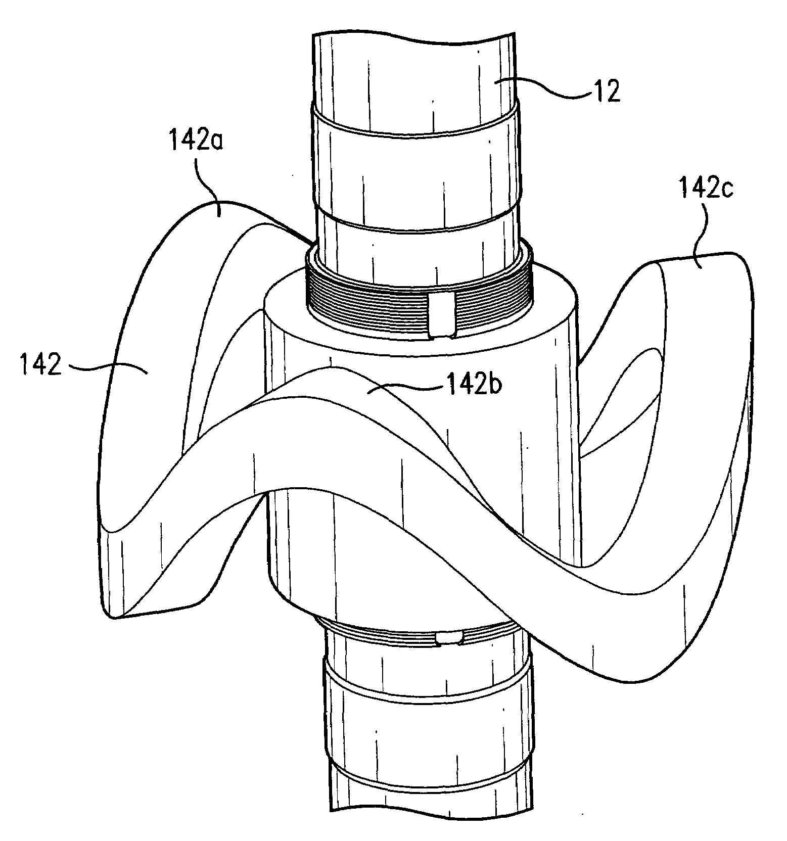
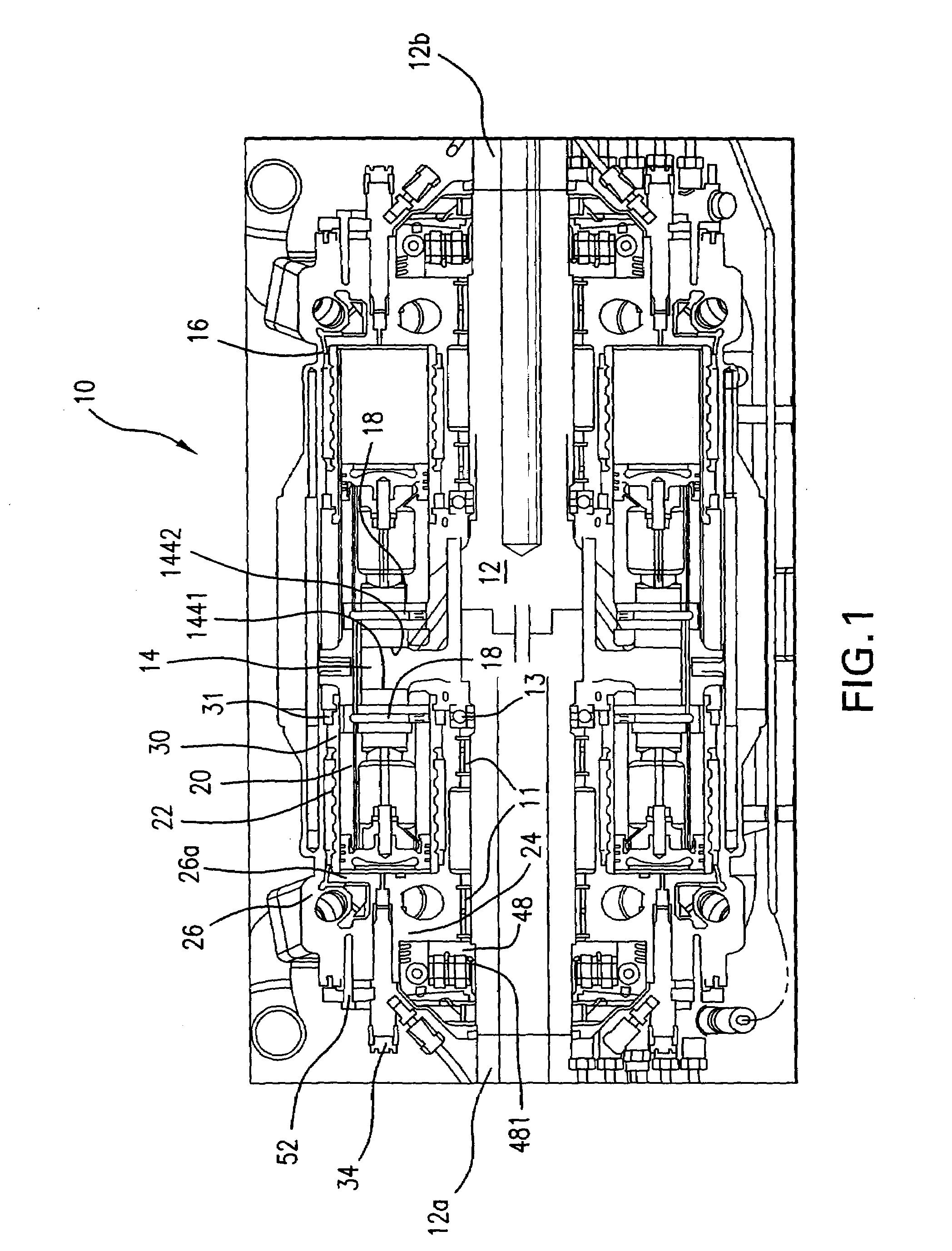
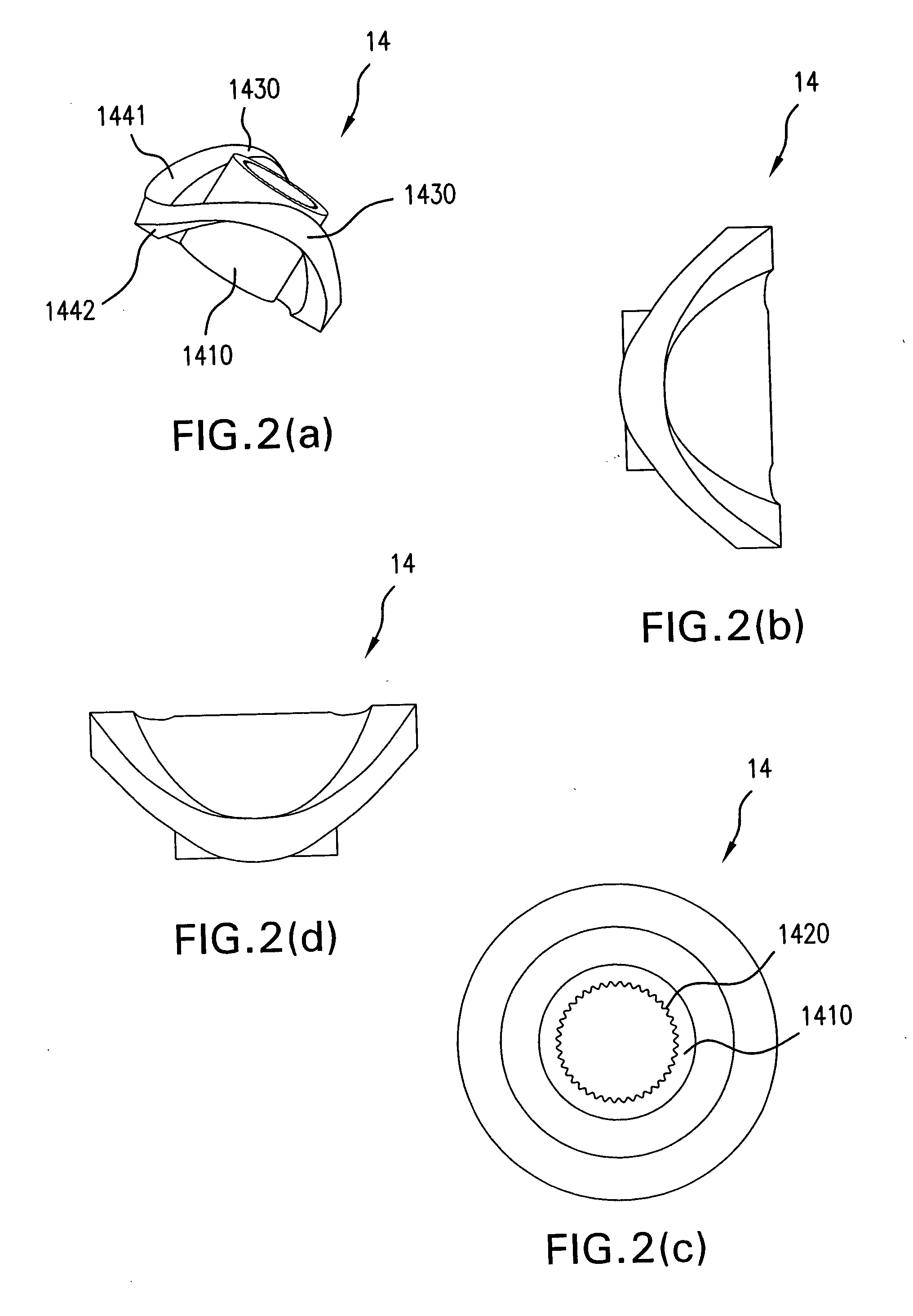
[0046]FIG. 1 is a cross-sectional view illustrating some of the features of an engine 10, e.g., a cam drive, barrel-type internal combustion engine, according to an example embodiment of the present invention. FIG. 1 illustrates the engine 10 including a main drive shaft 12 defining a longitudinal axis. The main drive shaft 12 may be formed of two shaft portions 12a and 12b that are connected to each other via a suitable coupling arrangement. Position of the main drive shaft 12 may be maintained with thrust bearings 13 and main shaft bearings 11. Rigidly attached to the main drive shaft 12 is a sinusoidal main drive cam 14. The main drive cam 14 may have varying shapes, dimensions and material properties based on, e.g., cost limitations or performance requirements, such as torque, fuel type, speed, etc., as set forth in additional detail below. It should be recognized that, while the main drive cam 14 is described herein as being sinusoidal, the main drive cam 14 may alternatively h...
PUM
Abstract
An engine, e.g., a cam drive, barrel-type internal combustion engine, that includes: a main drive shaft defining a longitudinal axis; a sinusoidal main drive cam rigidly attached to the main drive shaft; a plurality of cam members that are in contact with the sinusoidal main drive cam and that are configured to follow the sinusoidal main drive cam, wherein rotation of the sinusoidal main drive cam corresponds to reciprocating linear movement of each of the plurality of cam members in a direction parallel to the longitudinal axis; for each cam member, a pair of linear pistons disposed on opposite sides of the cam member for reciprocating linear movement within respective cylinder bores.
Description
CROSS-REFERENCE TO RELATED APPLICATIONS[0001]This application is related to U.S. patent application Ser. No. 11 / 493,710, entitled “Barrel-Type Internal Combustion Engine,” filed Jul. 24, 2006, U.S. patent application Ser. No. 11 / 523,188, entitled “Generator and / or Motor Assembly”, filed Sep. 18, 2006, and U.S. Provisional Patent Application Ser. No. 60 / 702,023, entitled “Barrel-Type Internal Combustion Engine,” filed Jul. 23, 2005, each of which is expressly incorporated herein in its entirety by reference thereto.FIELD OF THE INVENTION[0002]The present invention relates to internal combustion engines, and more particularly, to a cam drive, barrel-type internal combustion engine.BACKGROUND INFORMATION[0003]Various types of internal combustion engines are conventional. Some common types of internal combustion engines, e.g., Otto-, diesel-, Miller-, Atkinson-cycle, etc., may utilize pistons and connecting rods to drive a crankshaft. Rotary internal combustion engines, also referred to...
Claims
Application Information
Patent Timeline
Application Date:The date an application was filed.
Publication Date:The date a patent or application was officially published.
First Publication Date:The earliest publication date of a patent with the same application number.
Issue Date:Publication date of the patent grant document.
PCT Entry Date:The Entry date of PCT National Phase.
Estimated Expiry Date:The statutory expiry date of a patent right according to the Patent Law, and it is the longest term of protection that the patent right can achieve without the termination of the patent right due to other reasons(Term extension factor has been taken into account ).
Invalid Date:Actual expiry date is based on effective date or publication date of legal transaction data of invalid patent.
IPC IPC(8): F02B75/32
CPCF01B3/0005F02B75/26F01B3/0023
Inventor KUBES, LARRYVERNHES, PIERRE-LOUISLAMBERT, CHRISKLAVER, JEFFCAMPBELL, PETER