Barrel-type internal combustion engine

a barrel-type, internal combustion engine technology, applied in the direction of machines/engines, reciprocating piston engines, positive displacement engines, etc., can solve the problems that none of the existing cam-drive barrel-type internal combustion engines is believed to provide adequate performance, efficiency, versatility and compactness, and achieve the effect of minimizing engine vibration and minimizing thrust forces

Inactive Publication Date: 2008-05-08
KUBES LARRY +4
View PDF14 Cites 9 Cited by
  • Summary
  • Abstract
  • Description
  • Claims
  • Application Information

AI Technical Summary

Benefits of technology

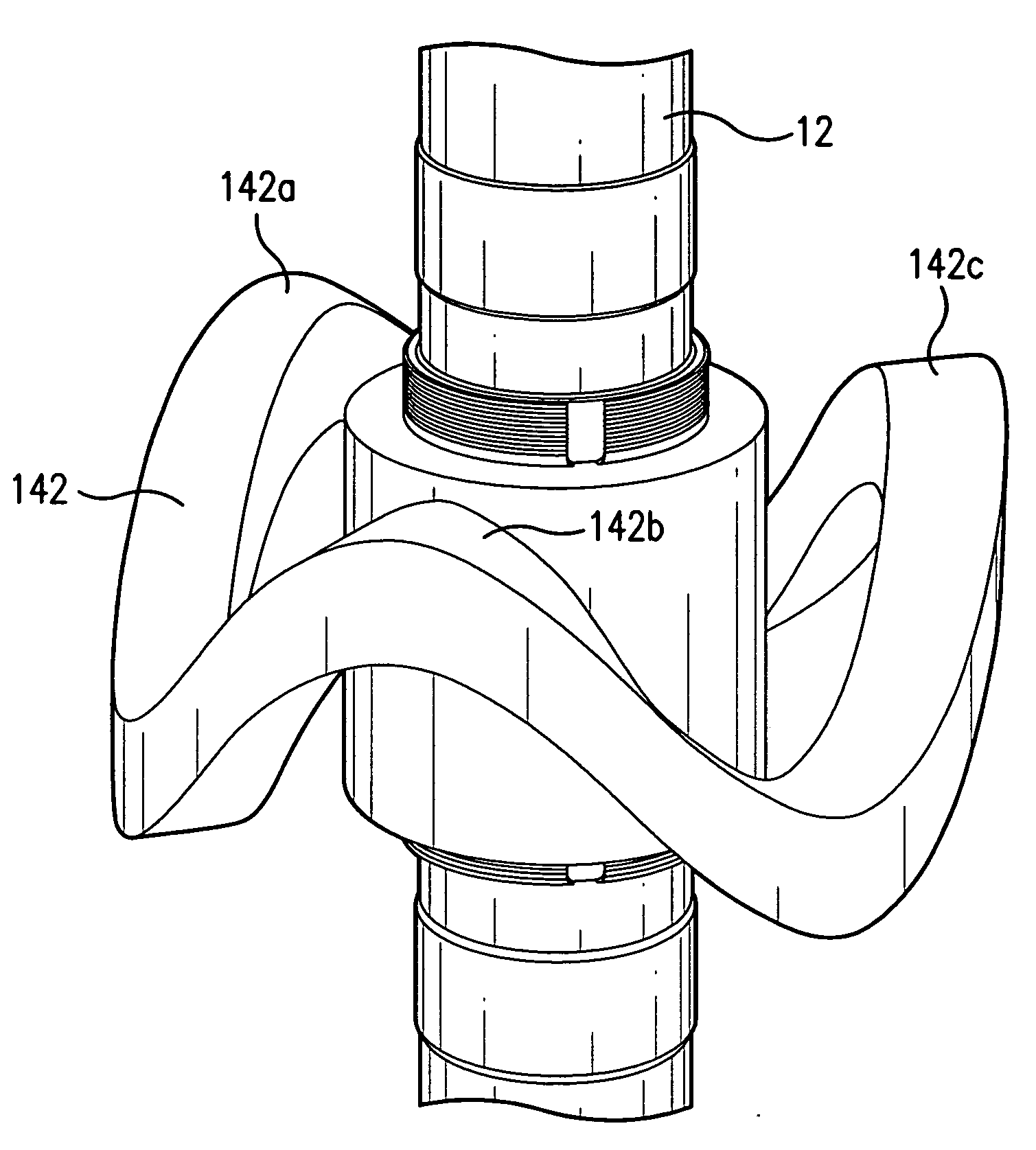
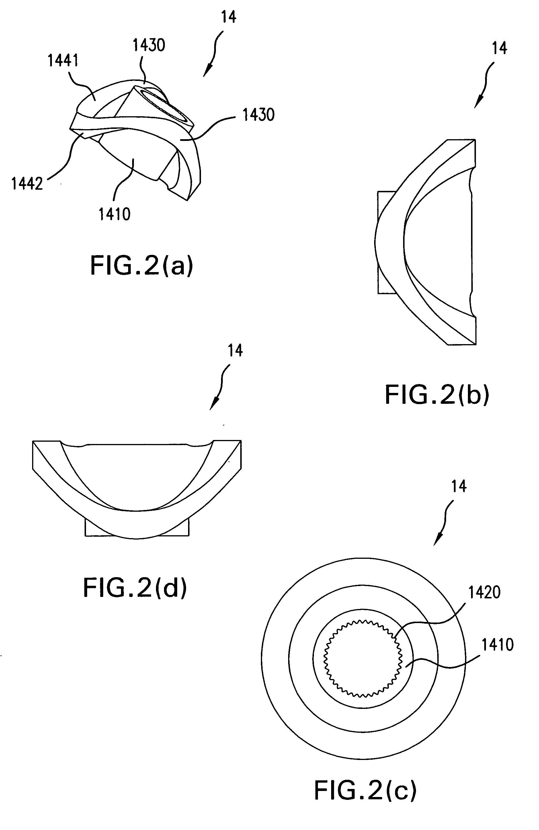
[0012]An engine may include: a main drive shaft defining a longitudinal axis; a sinusoidal main drive cam non-rotatably attached to the main drive shaft; four cylinder bores symmetrically arranged both radially and circumferentially about the longitudinal axis, a first portion of each cylinder bore being disposed on a first side of the sinusoidal main drive cam and a second portion of each cylinder bore being disposed on a second side opposite the first side of the sinusoidal main drive cam; a linear piston disposed in the first and second portions of each cylinder bore; mounted to each piston, a cam member that engages the sinusoidal main drive cam, wherein reciprocating linear movement of each piston and its respective cam member in a direction parallel to the longitudinal axis causes the respective cam member to rotate the sinusoidal main drive cam and the main drive shaft, such that the forces generated within the engine are substantially balanced, e.g., radial combustion forces are substantially or completely eliminated and axial combustion forces are opposed to each other such that net resultant forces are substantially or completely eliminated, so as to minimize engine vibration.
[0013]An engine may include: a main drive shaft defining a longitudinal axis; a sinusoidal main drive cam non-rotatably attached to the main drive shaft; four cylinder bores symmetrically arranged both radially and circumferentially about the longitudinal axis, a first portion of each cylinder bore disposed on a first side of the sinusoidal main drive cam and a second portion of each cylinder bore disposed on a second side opposite the first side of the sinusoidal main drive cam; a linear piston disposed in the first and second portions of each cylinder bore; mounted to each piston, a cam member that engages the sinusoidal main drive cam, wherein reciprocating linear movement of each piston and its respective cam member in a direction parallel to the longitudinal axis causes the respective cam member to rotate the sinusoidal main drive cam and the main drive shaft, such that the forces generated within the engine are substantially balanced, e.g., combustion in two opposed cylinders at the same time, so as to minimize thrust forces on the main drive shaft.

Problems solved by technology

However, none of the existing cam drive barrel-type internal combustion engines is believed to provide adequate performance, efficiency, versatility and compactness.

Method used


Image

  • Barrel-type internal combustion engine
  • Barrel-type internal combustion engine
  • Barrel-type internal combustion engine

Examples


Embodiment Construction

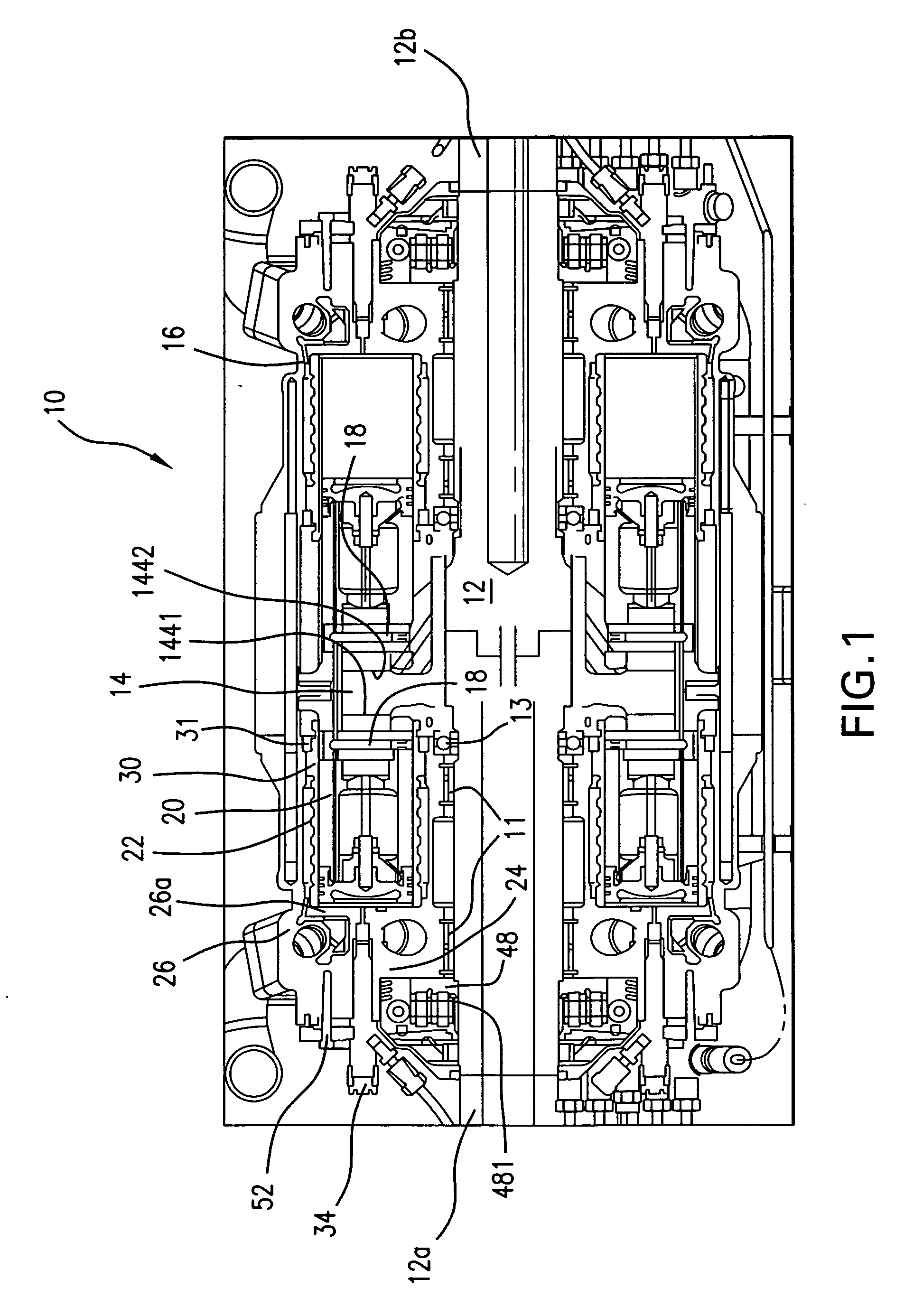
[0046]FIG. 1 is a cross-sectional view illustrating some of the features of an engine 10, e.g., a cam drive, barrel-type internal combustion engine, according to an example embodiment of the present invention. FIG. 1 illustrates the engine 10 including a main drive shaft 12 defining a longitudinal axis. The main drive shaft 12 may be formed of two shaft portions 12a and 12b that are connected to each other via a suitable coupling arrangement. Position of the main drive shaft 12 may be maintained with thrust bearings 13 and main shaft bearings 11. Rigidly attached to the main drive shaft 12 is a sinusoidal main drive cam 14. The main drive cam 14 may have varying shapes, dimensions and material properties based on, e.g., cost limitations or performance requirements, such as torque, fuel type, speed, etc., as set forth in additional detail below. It should be recognized that, while the main drive cam 14 is described herein as being sinusoidal, the main drive cam 14 may alternatively h...


PUM


Abstract

An engine, e.g., a cam drive, barrel-type internal combustion engine, that includes: a main drive shaft defining a longitudinal axis; a sinusoidal main drive cam rigidly attached to the main drive shaft; a plurality of cam members that are in contact with the sinusoidal main drive cam and that are configured to follow the sinusoidal main drive cam, wherein rotation of the sinusoidal main drive cam corresponds to reciprocating linear movement of each of the plurality of cam members in a direction parallel to the longitudinal axis; for each cam member, a pair of linear pistons disposed on opposite sides of the cam member for reciprocating linear movement within respective cylinder bores.

Description

CROSS-REFERENCE TO RELATED APPLICATIONS[0001]This application is related to U.S. patent application Ser. No. 11 / 493,710, entitled “Barrel-Type Internal Combustion Engine,” filed Jul. 24, 2006, U.S. patent application Ser. No. 11 / 523,188, entitled “Generator and / or Motor Assembly”, filed Sep. 18, 2006, and U.S. Provisional Patent Application Ser. No. 60 / 702,023, entitled “Barrel-Type Internal Combustion Engine,” filed Jul. 23, 2005, each of which is expressly incorporated herein in its entirety by reference thereto.FIELD OF THE INVENTION[0002]The present invention relates to internal combustion engines, and more particularly, to a cam drive, barrel-type internal combustion engine.BACKGROUND INFORMATION[0003]Various types of internal combustion engines are conventional. Some common types of internal combustion engines, e.g., Otto-, diesel-, Miller-, Atkinson-cycle, etc., may utilize pistons and connecting rods to drive a crankshaft. Rotary internal combustion engines, also referred to...

Claims


Application Information

Patent Timeline
Patent Type & Authority Applications(United States)
IPC IPC(8): F02B75/00
CPCF01B3/0005F02B75/26F01B3/0023
Inventor KUBES, LARRYVERNHES, PIERRE-LOUISLAMBERT, CHRISKLAVER, JEFFCAMPBELL, PETER
Owner KUBES LARRY
Why Eureka
Try Eureka