Universal Joint

Inactive Publication Date: 2008-05-08
FAUDE DIETER
View PDF13 Cites 18 Cited by
  • Summary
  • Abstract
  • Description
  • Claims
  • Application Information

AI Technical Summary

Benefits of technology

[0004]In contrast, the inventive universal joint has the advantage that a bearing prestress unit allows the joint forks to function without play about the joint axis the

Problems solved by technology

However, it is disadvantageous that production-imposed tolerances can lead to distortions or that there can be too much play, which has a negative effect on the operational reliability of the bearing and on the

Method used


Image

  • Universal Joint
  • Universal Joint
  • Universal Joint

Examples


Embodiment Construction

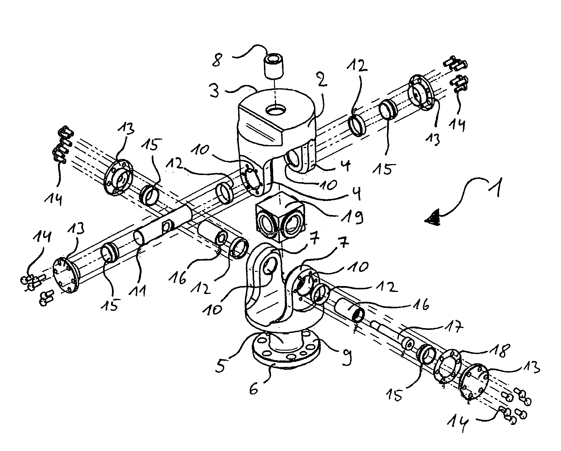
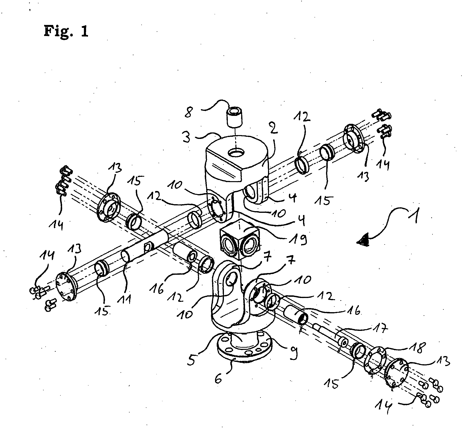
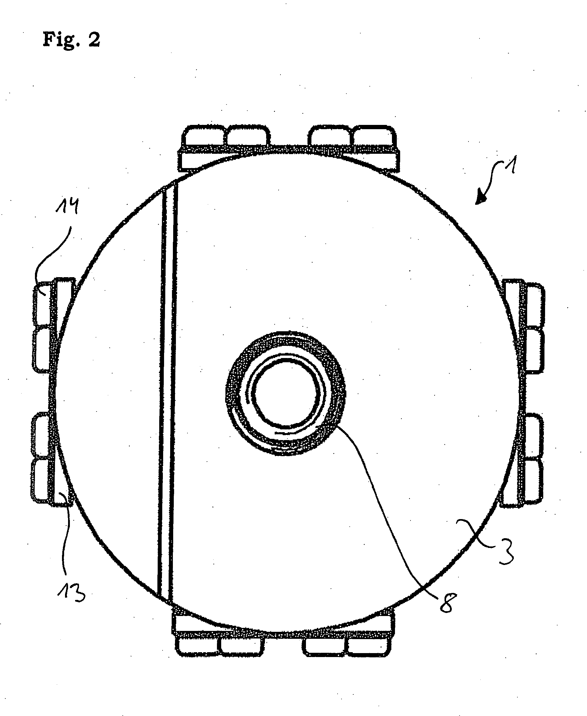
[0035]FIG. 1 is an exploded depiction of an inventive universal joint 1. It comprises a first joint fork 2, which constitutes a base part 3 and two fork elements 4, and a second joint fork 5, which constitutes a base part 6 and two fork elements 7. The base part 3 has a threaded insert 8 and acts for instance as a connecting part for a Stuart plate (not shown). It can have a hard-coated surface plain bearing and ground interior sides and is a bearing element for the entire bearing. The base part 6 has a flange 9 and acts for instance as an interface to different materials e.g. a carbon tube (not shown). If there is wear or if the inventive universal joint 1 is destroyed, it is possible to exchange it easily using the base parts 3 and 6. The fork elements 4 and 7 each have bores 10 in their joint axes. The joint axis of the first joint fork 2 is formed by a pin 11 that is borne in the bores 10 of the first joint fork 2 by bearing rings 12 (plain bearings). These bearing rings 12 have...


PUM


Abstract

A universal joint includes a first joint fork having a joint axis and a second joint fork having a joint axis, the joint axes being borne by plain bearings and the joint forks each being formed by a base part and two fork elements. Each fork element has a closable bore, and the joint axes intersect between the bores, whereby a bearing prestress unit allows the joint fork to function without play about the joint axis thereof so that the universal joint can be positioned precisely.

Description

BACKGROUND OF THE INVENTION[0001]The invention relates to a universal joint.[0002]As a rule, such universal joints have a roller or plain bearing. However, it is disadvantageous that production-imposed tolerances can lead to distortions or that there can be too much play, which has a negative effect on the operational reliability of the bearing and on the accuracy of the universal joint and the positioning thereof.[0003]Known from DE 44 39 998 A1 is a universal joint that, for connecting two joint forks, has a cross link assembly made of four journals, two journals being located on a common axis. Each axis is borne by means of a roller bearing on a bearing bush and has a spring element made of a high-strength plastic. A tolerance imposed by the assembly is supposed to be compensated using the spring element. However, the spring element also enables the journal in the bearing bush to yield so that the universal joint can no longer be positioned accurately.SUMMARY OF THE INVENTION[000...

Claims


Application Information

Patent Timeline
IPC IPC(8): F16D3/00
CPCF16D3/40F16D3/385
Inventor FAUDE, DIETER
Owner FAUDE DIETER
Why Eureka
Try Eureka