Methods and Apparatus for Intervertebral Disc Prosthesis Insertion

a technology of intervertebral discs and prostheses, applied in the field of medical devices and methods, can solve the problems of limiting the load bearing area between the plates and the core, and achieve the effects of reducing distraction, avoiding tissue trauma, and minimising or reducing intervertebral distraction

Active Publication Date: 2008-06-26
SIMPLIFY MEDICAL PTY LTD
View PDF101 Cites 94 Cited by
  • Summary
  • Abstract
  • Description
  • Claims
  • Application Information

AI Technical Summary

Benefits of technology

[0016]The present invention generally provides methods for inserting an intervertebral disc prosthesis, as well as devices and systems for performing the methods. One advantage of these improved methods is that a disc prosthesis may be inserted with minimal or reduced intervertebral distraction, thus avoiding trauma to tissues in and around the insertion site. Reduced distraction is generally achieved by inserting a prosthesis into an intervertebral space while allowing endplates of the prosthesis to articulate during at least part of the insertion process. For the purposes of this application, to “articulate” means to move relative to another structure. Thus, allowing endplates of an intervertebral prosthesis to articulate means that endplates are free to move relative to each other, relative to a core of the prosthesis, relative to a ball and socket joint of the prosthesis, relative to a mobile or fixed center of rotation of the prosthesis and / or the like. Although the following description often focuses on disc prostheses having two endplates and a core, various embodiments of the insertion method may be applied to any other intervertebral disc prosthesis. Articulation of the endplates during insertion allows the prosthesis to be pushed posteriorly into a disc space without excessive intervertebral distraction or significant forces being applied to the vertebrae, thus achieving desirable positioning of the prosthesis while avoiding trauma to surrounding muscles, ligaments, nerves and the like.
[0017]In one aspect of the present invention, a method of inserting an intervertebral prosthesis into a space between two adjacent vertebrae involves inserting the prosthesis partway into the space under constraint to prevent endplates of the prosthesis from articulating, releasing the prosthesis from constraint, and inserting the unconstrained prosthesis farther into the space. As mentioned above, in some embodiments, the endplates of the constrained prosthesis are prevented from articulating about a core of the prosthesis, while the endplates of the unconstrained prosthesis are generally free to articulate about the core to help the prosthesis conform to the space between the two vertebrae. In alternative embodiments, the unconstrained endplates may be free to articulate about a ball and socket joint or other structure.

Problems solved by technology

Such arrangements limit the load bearing area available between the plates and core.

Method used


Image

  • Methods and Apparatus for Intervertebral Disc Prosthesis Insertion
  • Methods and Apparatus for Intervertebral Disc Prosthesis Insertion
  • Methods and Apparatus for Intervertebral Disc Prosthesis Insertion

Examples


Embodiment Construction

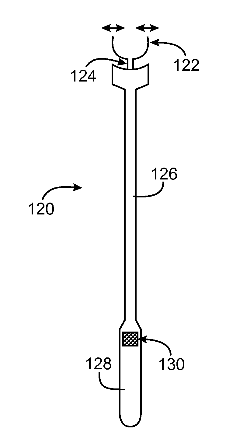
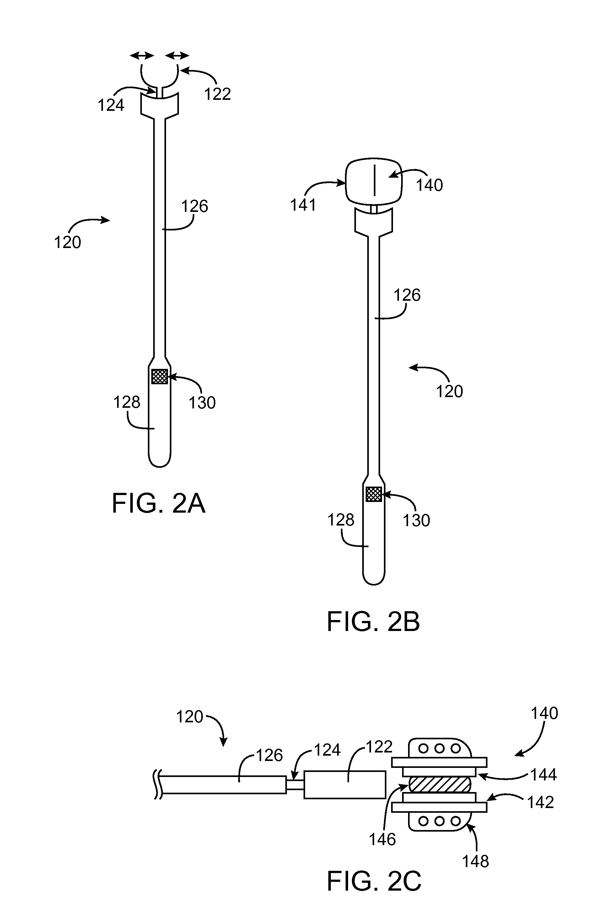
[0038]Referring to FIGS. 1A-1E, in one embodiment a method for inserting an intervertebral disc prosthesis 104 into an intervertebral space IS between two adjacent vertebrae V first involves inserting the disc prosthesis 104 partway into the space IS while the prosthesis 104 is constrained (FIG. 1A). By “constrained” it is meant that endplates 106 of the prosthesis 104 are not free to articulate (move) about a core 112 (FIGS. 1B-1E) of the prosthesis 104. To insert the prosthesis 104 partway under constraint, an insertion device 102 may be used. Such an insertion device 102 may suitably include a grasping member 110 coupled with an elongate shaft 108. At an end opposite the grasping member 110 (not shown), the insertion device 102 may include a handle, an actuator to control the grasping member 110 and / or any other suitable features, some of which are described further below.

[0039]The prosthesis 104 may be inserted as far into the intervertebral space IS under constraint as is desir...


PUM


Abstract

A method for inserting an intervertebral disc prosthesis into a space between two vertebrae involves inserting the prosthesis partway into the space under constraint to prevent endplates of the prosthesis from articulating, releasing the prosthesis from constraint, and inserting the unconstrained prosthesis farther into the space. In some embodiments, the method involves grasping the prosthesis with a grasping device to insert the prosthesis partway under constraint, loosing the grasping device to release the prosthesis from constraint, and pushing the prosthesis farther into the disc space using the grasping device and / or one or more separate pusher devices. A system includes a grasping device, at least one separate pushing device, and optionally a vertebral spreading device and / or a vertebral midline indicator device.

Description

CROSS REFERENCE TO RELATED APPLICATION DATA[0001]The present application is a divisional of U.S. patent application Ser. No. 10 / 913,780 filed Aug. 6, 2004, the full disclosure of which is incorporated herein by reference.BACKGROUND OF THE INVENTION[0002]1. Field of the Invention[0003]This invention relates to medical devices and methods. More specifically, the invention relates to intervertebral disc prostheses.[0004]Back pain takes an enormous toll on the health and productivity of people around the world. According to the American Academy of Orthopedic Surgeons, approximately 80 percent of Americans will experience back pain at some time in their life. In just the year 2000, approximately 26 million visits were made to physicians' offices due to back problems in the United States. On any one day, it is estimated that 5% of the working population in America is disabled by back pain.[0005]One common cause of back pain is injury, degeneration and / or dysfunction of one or more interve...

Claims


Application Information

Patent Timeline
Patent Type & Authority Applications(United States)
IPC IPC(8): A61F2/44A61B19/00A61B17/58
CPCA61B2017/0256A61F2/4611A61F2002/4628A61F2002/4622A61F2002/4627A61F2002/443A61B17/28A61B17/88A61F2/46A61B17/025A61F2/442A61F2/4425A61F2/4455A61F2/4465A61F2/4603A61F2002/30518A61F2002/30649A61F2002/4615
Inventor DE VILLIERS, MALANHAHNLE, ULRICHHOVDA, DAVID
Owner SIMPLIFY MEDICAL PTY LTD
Why Eureka
Try Eureka