Microneedle roller

a micro-needle roller and micro-needle technology, applied in the field of micro-needle rollers, can solve the problems of more skin wrinkles, acute skin pain, dry skin, etc., and achieve the effects of long service life, good maintainability, and substantial skin pain reduction

Inactive Publication Date: 2008-07-03
LEE JUSTIN +1
View PDF8 Cites 30 Cited by
  • Summary
  • Abstract
  • Description
  • Claims
  • Application Information

AI Technical Summary

Benefits of technology

[0011]An objective of the invention is to provide a microneedle roller that induces substantially less pain to the skin and having durable microneedles.
[0012]Another objective of the invention is to provide a microneedle roller that has good maintainability.

Problems solved by technology

As the result, the skin gets dry, and more skin wrinkles appear.
Microneedle rollers by prior art have disadvantages that they induce acute pain to the skin since their ends are too sharp, the ends of the microneedle rollers are not durable, the skin is not stimulated uniformly, and the microneedles fall off from the roller.
The microneedle roller should be disposed together with the handle since it is difficult to separate the roller from the handle.

Method used


Image

  • Microneedle roller
  • Microneedle roller
  • Microneedle roller

Examples


Embodiment Construction

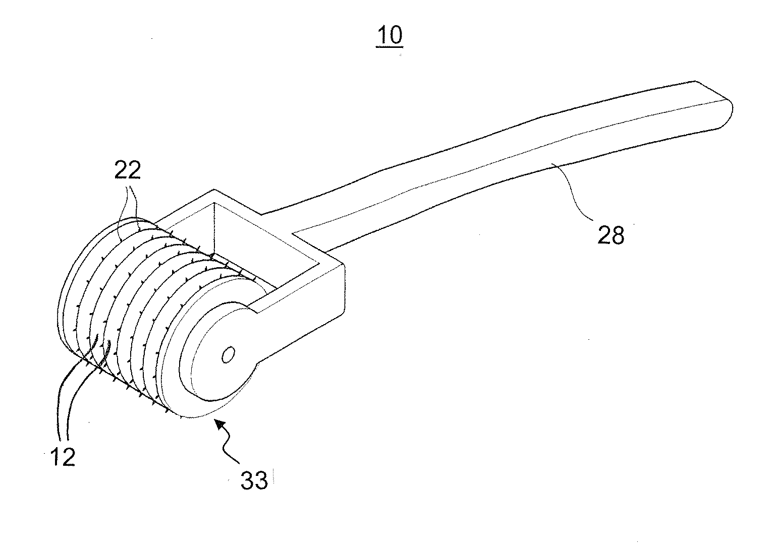
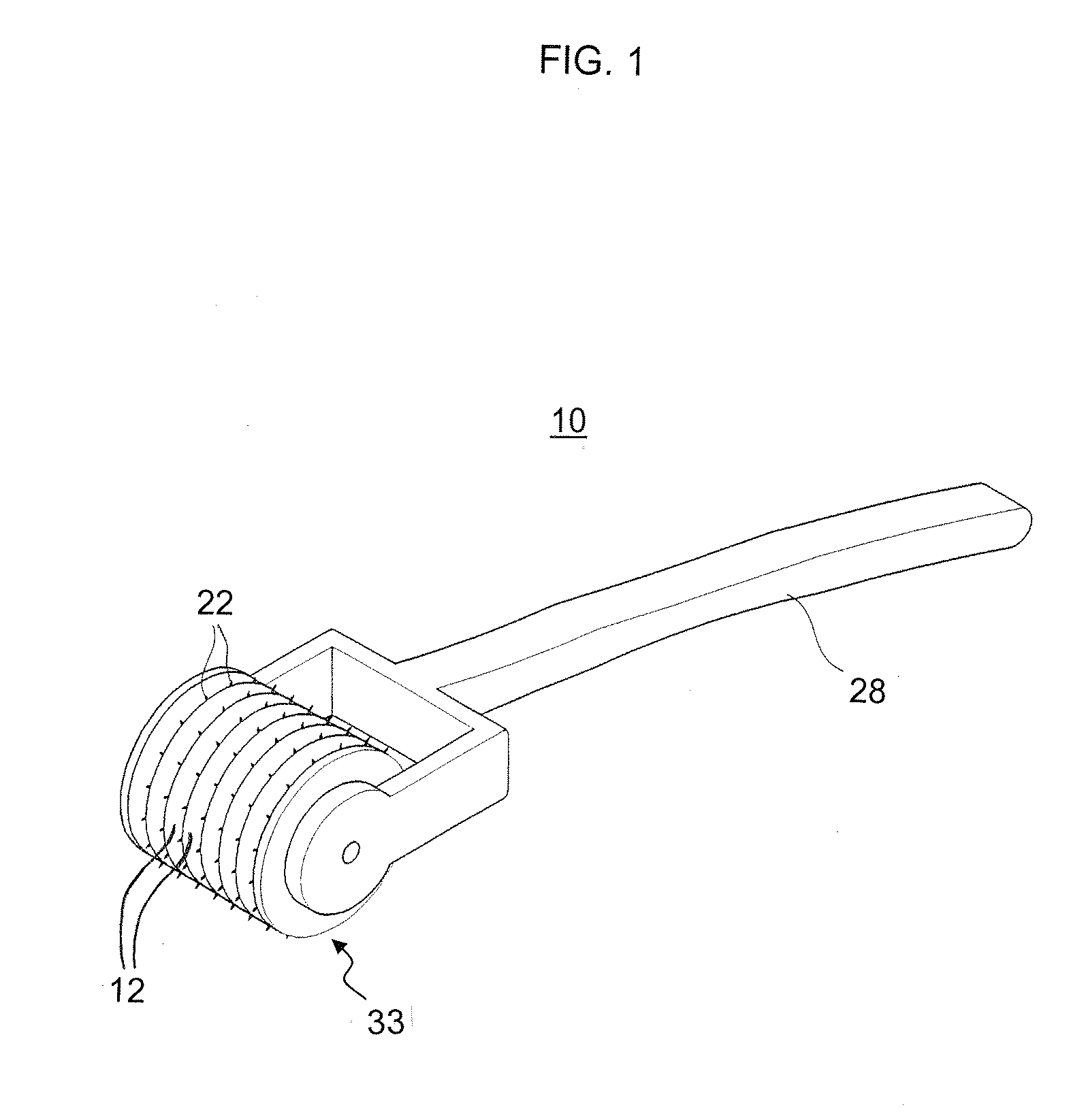
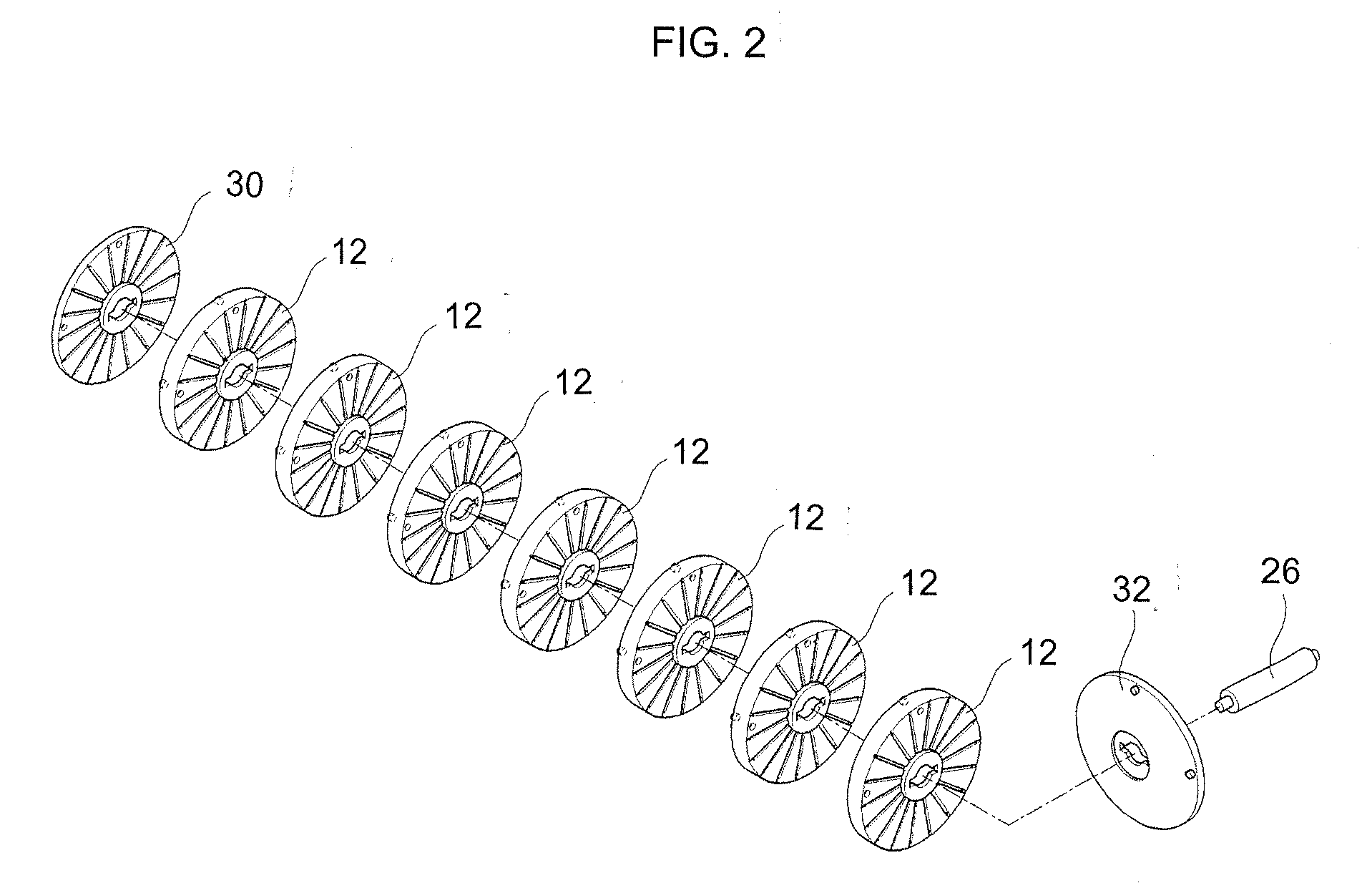
[0031]FIGS. 1 and 2 show a microneedle roller 10 that includes a plurality of discs 12, each of which comprises a first side surface 14, a second side surface 16 and a center hole 18 (refer to FIG. 3).

[0032]The first side surface 14 comprises a plurality of radial grooves 20, and the discs 12 are stacked on one another in a way that the first side surface 14 of one disc 12 contacts the second side surface 16 of the adjacent disc 12 as shown in FIG. 2.

[0033]The microneedle roller10 further includes a plurality of microneedles 22 that are received in the radial grooves 20 of the discs 12, and each of which has a pointed end 24 (refer to FIG. 5). The pointed end 24 protrudes beyond the circumference of the disc 12 as shown in FIG. 1.

[0034]The microneedle roller 10 further includes an axis shaft 26 that passes thorough the center holes 18 of the stacked discs 12 and a handle 28 that detachably supports both ends of the axis shaft 26. The discs 12, the microneedles 22, the axis shaft 26 ...


PUM


Abstract

A microneedle roller includes a plurality of discs, each of which comprises a first side surface, a second side surface and a center hole. The first side surface comprises a plurality of radial grooves, and the discs are stacked on one another in a way that the first side surface of one disc contacts the second side surface of the adjacent disc. The microneedle roller further includes a plurality of microneedles that are received in the radial grooves of the disc, and each of which has a pointed end. The pointed end protrudes beyond the outer circumference of the disc. The microneedle comprises an elongated cylindrical needle shank, a first sloped portion that starts from the pointed end, and a second sloped portion that is provided between the first sloped portion and the second sloped portion. The angle of the first sloped portion is greater.

Description

CLAIMING FOREIGN PRIORITY[0001]The applicant claims and requests a foreign priority, through the Paris Convention for the Protection of Industrial Property, based on patent applications filed in the Republic of Korea (South Korea) with the filing date of Dec. 20, 2006 with the patent application number 10-2006-0131238 by the applicant, the contents of which are incorporated by reference into this disclosure as if fully set forth herein.BACKGROUND OF THE INVENTION[0002]The present invention relates to a microneedle roller.[0003]More particularly, the present invention relates to a microneedle roller that reduces pain of the skin, has durable microneedles, and stimulates the skin uniformly.[0004]The skin of a human being is composed of three primary layers, the epidermis, the dermis and the appendages. Among them, the dermis forming skin wrinkles is disposed under the epidermis as the lowest skin layer at a thickness of about 0.7 mm to 4 mm. Collagen in the dermis shrinks as the aging...

Claims


Application Information

Patent Timeline
Patent Type & Authority Applications(United States)
IPC IPC(8): A61H15/00
CPCA61H15/0092A61H2015/0035A61M2037/0023A61M37/0015A61H2201/1695A61M37/00
Inventor LEE, JUSTINHONG, SOON IL
Owner LEE JUSTIN
Why Eureka
Try Eureka