Electrical connector

a technology of electrical connectors and connectors, applied in the direction of coupling devices, two-part coupling devices, electrical apparatus, etc., can solve the problems of defective or failed connection between electrical connectors and mating connectors, affecting the connection of coupling devices, and reducing the size of crush ribs, so as to prevent any defective or failed connection

Inactive Publication Date: 2008-09-04
DDK LTD
View PDF5 Cites 5 Cited by
  • Summary
  • Abstract
  • Description
  • Claims
  • Application Information

AI Technical Summary

Benefits of technology

[0009]The present invention has been completed in view of the problems of the prior art and has an object to provide an electrical connector which enables its positioning relative to a mating connector with great certainty when fitting with a m

Problems solved by technology

Moreover, with the miniaturization of the connectors, the interference (size of crush ribs) for press-fitting has become smaller.
With such a construction disclosed in the prior art, when the electrical connector is being fitted with the mating connector, the housing woul

Method used


Image

  • Electrical connector
  • Electrical connector
  • Electrical connector

Examples


Embodiment Construction

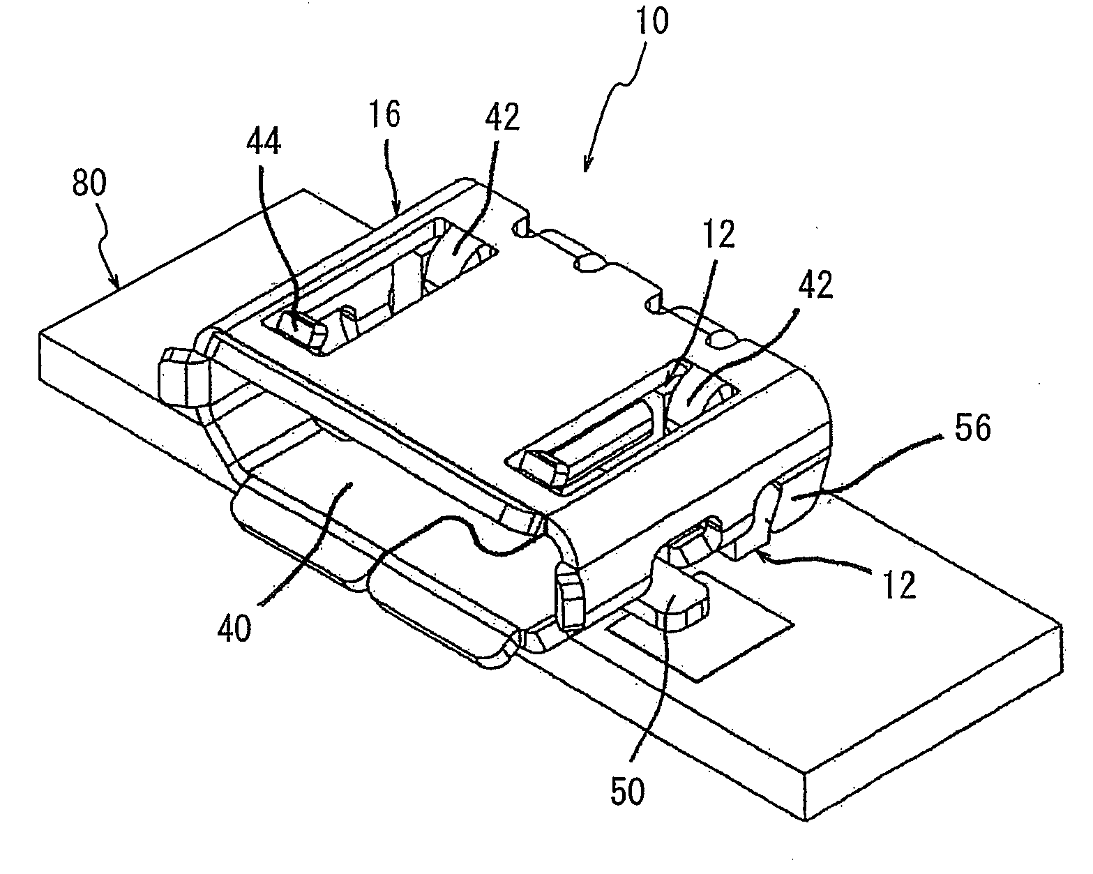
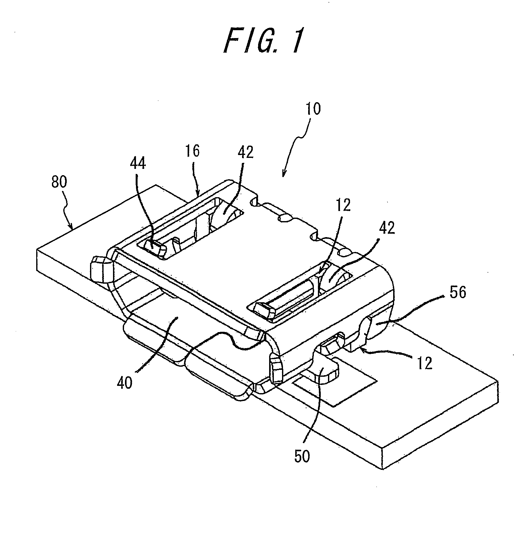
[0034]The electrical connector 10 according to the invention will be explained with reference to FIGS. 1 to 5 (B). FIG. 1 is a perspective view of the electrical connector according to the invention connected to a substrate viewed from its fitting side. FIG. 2 (A) is a perspective view of a shell of the electrical connector viewed from the fitting side, while FIG. 2 (B) is a perspective view of the shell viewed from its connecting side. FIG. 3 (A) is a perspective view of a housing of the electrical connector with contacts inserted, viewed from the fitting side, and FIG. 3 (B) is a perspective view of the housing with the contacts inserted, viewed from the connecting side. FIG. 4 is a perspective view of the contact. FIG. 5 (A) is a perspective view of the shell viewed from the side of the fitting opening before the housing is inserted, while FIG. 5 (B) is a perspective view of the shell viewed from the connecting side before the housing is inserted. FIG. 6 (A) is a perspective view...


PUM


Abstract

An electrical connector to be detachably fitted with a mating connector, including a plurality of contacts, a housing for arranging and holding the contacts, and a shell covering the housing and forming with the housing a fitting opening for the mating connector. The shell has at least one engaging piece, and the housing has an anchoring portion at a location corresponding to the engaging piece to cause the anchoring portion to engage the engaging piece, thereby restraining the housing from being displaced in the direction opposite to the fitting direction upon fitting with the mating connector. Even being miniaturized, the electrical connector is securely positioned relative to the mating connector when fitting with it, and the housing is securely prevented from being displaced upon the mating connector abutting against the housing, thereby completely preventing any defective connection.

Description

BACKGROUND OF THE INVENTION[0001]This invention relates to an electrical connector for use in electric and electronic appliances such as mobile phones, and more particularly to an electrical connector with a structure for preventing a housing from being pushed when fitting with a mating connector.[0002]An electrical connector hitherto used will be explained. The electrical connector comprises at least a plurality of contacts to be connected to a substrate, a housing for arranging and holding said contacts, and a shell having holding means for covering and holding said housing.[0003]Said housing is fitted into said shell by press-fitting (with crush ribs) so as to be held in (fixed to) said shell, and when a mating connector is being fitted with the electrical connector, the mating connector is positioned by its abutment against said housing. As examples of electrical connectors, incorporated herein are three patent literatures: Patent Literature 1 (Japanese Patent Application Opened...

Claims


Application Information

Patent Timeline
IPC IPC(8): H01R13/648
CPCH01R12/716H01R23/6873H01R13/658
Inventor ISHIZUKA, SHINYAYAMADA, AKIOOZAI, KAZUYUKIKATO, HIROMICHI
Owner DDK LTD
Why Eureka
Try Eureka