Cushioning Means Holding Member, and Slide Switch Including the Same

a technology of holding member and slide switch, which is applied in the direction of contact vibration/shock damping, electrical equipment, contact vibration/shock damping, etc., can solve the problems of bad operation feeling and slide switch vibration noise, and achieve the effect of reducing the generation of slide switch vibration noise and improving the operation feeling of the vehicl

Active Publication Date: 2008-10-02
MIYAMA ELECTRIC CO LTD
View PDF6 Cites 8 Cited by
  • Summary
  • Abstract
  • Description
  • Claims
  • Application Information

AI Technical Summary

Benefits of technology

[0022]According to the invention recited in claim 7, because the slider has a protruding part protruding from the lower face of the slider body and the protruding part is supported by the elastic member such as a coil spring, the upward-downward movement of t

Problems solved by technology

Thus, the slide switch generates vibration noise due to vibration of a vehicle under trave

Method used


Image

  • Cushioning Means Holding Member, and Slide Switch Including the Same
  • Cushioning Means Holding Member, and Slide Switch Including the Same
  • Cushioning Means Holding Member, and Slide Switch Including the Same

Examples


first embodiment

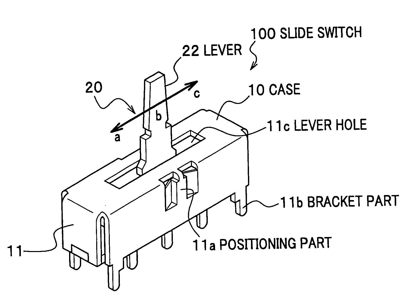
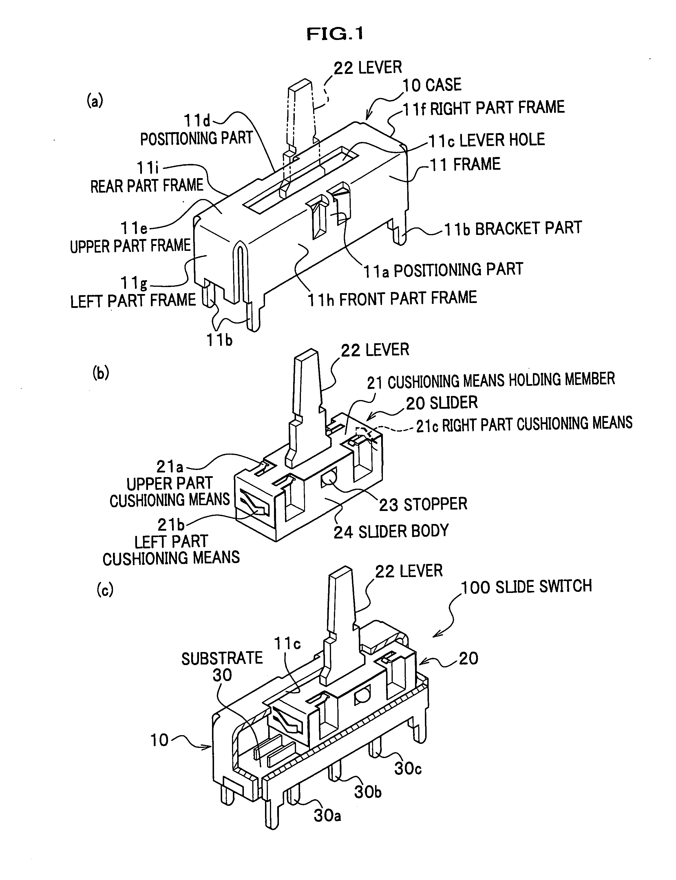
[0031]Hereinbelow with reference to drawings will be described a first embodiment of the present invention. FIG. 1 shows an internal configuration of a slide switch 100 according to the first embodiment of the present invention. FIG. 1 (a) is a perspective view illustrating a case. FIG. 1 (b) is a perspective view of a slider. FIG. 1 (c) is a perspective view of the slide switch assembled to include the case and the slider and partially cut.

[0032]As shown in FIG. 1, the slide switch 100 is configured with a case 10, a slider 20, and a substrate 30.

[0033]As shown in FIG. 1 (a), the case 10 is configured with a frame 11 of which five faces are surrounded and of which one face is opened. The frame 11 is formed by a process of folding a plate member, i.e., the frame 11 is subject to the folding process to form a front part frame 11h, a rear part frame 11i, a left part frame 11g, a right part frame 11f, and an upper part frame 11e.

[0034]Here, “front / rear”, “right / left”, and “upper / lower...

second embodiment

[0065]FIG. 6 shows an internal configuration of the slide switch 300 according to a second embodiment of the present invention. FIG. 6 (a) is a perspective view illustrating a slider. FIG. 6 (b) is a configuration drawing illustrating an operation of the slide switch in which a case and the slider are assembled.

[0066]A difference in the second embodiment from the first embodiment is, in contrast to the first embodiment in which the energizing force is applied to an upper part of the slider by the leaf springs, that the energizing force is generated at upper and lower parts of the slider 50. Thus, in the second embodiment, the same elements are designated with the same references as the first embodiment, and the detailed descriptions are omitted.

[0067]As shown in FIGS. 6 (a) and 6 (b), the slide switch 300 is configured with a case 40, the slider 50, and a substrate 60. The slider 50 includes a slider body 54, a cushioning means holding member 51, a stopper 53, and a lever 52.

[0068]A...


PUM


Abstract

A slide switch 100 according to the present invention includes a slider 20, a case 10 into which the slider 20 is inserted, performing switching by a sliding operation of the slider 20, cushioning means (an upper part, a left part, and a right part) 21a, 21b, and 21c, provided at contacting places in the side of the slider where the slider 20 and the case 10 come into contact by the sliding operation of the slider 20 for relieving the contact, and a cushioning means holding member 21 for integrally supporting the cushioning means, wherein the case 10 has case inner faces on which the slider 20 slides, and which face each other along a horizontal direction, one of the inner faces of the case 10 has a positioning part 11a for positioning the slider 20 at three positions, and the other of the inner faces of the case 10 has a positioning part 11d for positioning the slider 20 at two positions.
This can reduce generation of vibration noise of the slide switch due to vibration of a vehicle under running and operation noise due to a switching operation to improve an operation feeling of the vehicle.

Description

TECHNICAL FIELD[0001]The present invention relates to a cushioning means holding member and a slide switch including the same, and particularly to a cushioning means holding member including a slider which slides within the slide switch by a lever, and a case into which the slider is inserted for performing switching by a sliding operation of the slider and a slide switch including the same.BACKGROUND ART[0002]Conventionally, a slide switch is disclosed which relieves, by a cushioning function of a leaf spring mounted on a case or a slider, contact occurring when a slider sliding within the slide switch and the case housing the slider come into contact with each other in order to reduce operation noise generated by a switch operation of the slide switch (see, for example, Japanese laid-open patent application publication No. 2002-42608). Whenever the lever of the slide switch is moved in a horizontal direction, the slider slides, so that terminals of the slide switch turn on and off...

Claims


Application Information

Patent Timeline
IPC IPC(8): H01H1/36H01H3/60H01H15/02
CPCH01H3/60H01H15/02
Inventor MIKI, TORU
Owner MIYAMA ELECTRIC CO LTD
Why Eureka
Try Eureka