Movement device

a technology of moving device and supporting body, which is applied in the direction of vehicle safety belts, vehicle components, gearing, etc., can solve the problem of rotatably supporting the supporting body, and achieve the effect of suppressing the generation of sliding noise between the restricting body and the rotating supporting body

Active Publication Date: 2020-10-20
KK TOKAI RIKA DENKI SEISAKUSHO
View PDF12 Cites 0 Cited by
  • Summary
  • Abstract
  • Description
  • Claims
  • Application Information

AI Technical Summary

Benefits of technology

[0005]In view of the above-described circumstances, an object of the present invention is to provide a movement device that can suppress offset between the rotation central axis of a supporting member and the rotation central axis of a rotating member.
[0011]Here, the restricting body restricts movement of the supporting portion and restricts movement of the rotating member in the rotation axial direction. Therefore, at the time when the restricting body restricts movement of the rotating member in the rotation axial direction, the supporting portion sliding with respect to the restricting body can be suppressed, and generation of sliding noise between the restricting body and the rotation supporting body can be suppressed.

Problems solved by technology

Further, the supporting body rotatably supports the rotating member.

Method used


Image

  • Movement device
  • Movement device

Examples


Embodiment Construction

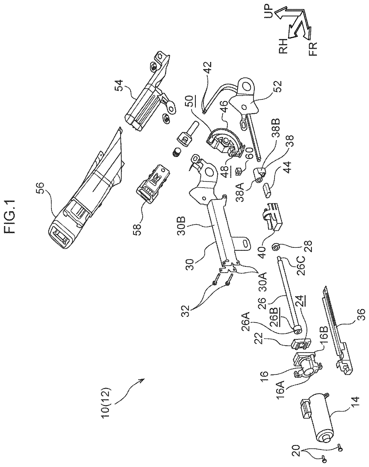
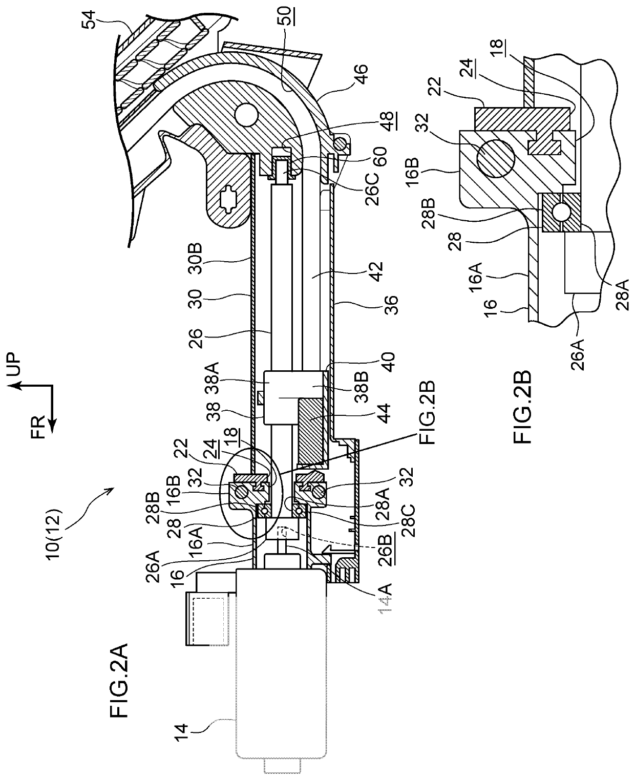
[0016]A lift-up buckle device 10, which serves as a movement device relating to an embodiment of the present invention, is shown in FIG. 1 in an exploded perspective view seen from an oblique front and left side. The lift-up buckle device 10 is shown in FIG. 2A in a cross-sectional view seen from the left. Note that, in the drawings, the front of the lift-up buckle device 10 is indicated by arrow FR, the right of the lift-up buckle device 10 is indicated by arrow RH, and the upward direction of the lift-up buckle device 10 is indicated by arrow UP.

[0017]The lift-up buckle device 10 relating to the present embodiment structures a seatbelt device 12 of a vehicle (an automobile). The seatbelt device 12 is applied to a seat (not illustrated) that is within a vehicle cabin. A seating sensor (not illustrated) is provided at the seat. The seating sensor detects that a vehicle occupant is seated in the seat, and is electrically connected to a control device (not illustrated).

[0018]The seatb...


PUM


Abstract

At a lift-up buckle device, due to a motor being driven and an output shaft of the motor being rotated, a drive screw is rotated. Further, a supporting tube rotatably supports a rear end portion of the drive screw. Here, the output shaft rotatably supports a front end portion of the drive screw. Therefore, offset between a rotation central axis of the output shaft and a rotation central axis of the drive screw can be suppressed.

Description

CROSS-REFERENCE TO RELATED APPLICATION[0001]This application is based on and claims priority under 35 USC 119 from Japanese Patent Application No. 2017-4563 filed on Jan. 13, 2017, the disclosure of which is incorporated by reference herein.BACKGROUNDTechnical Field[0002]The present invention relates to a movement device in which a rotating member is rotated and a moving body is moved.Related Art[0003]In the buckle movement device disclosed in Japanese Patent Application Laid-Open (JP-A) No. 2012-131360, due to a motor being driven and a screw joint being rotated, a drive screw is rotated, and an anchor slider is moved. Further, the drive screw is rotatably supported by a first bush and a second bush.[0004]Here, in such a buckle movement device, it is preferable to suppress offset between the rotation central axis of the screw joint and the rotation central axis of the drive screw.SUMMARY[0005]In view of the above-described circumstances, an object of the present invention is to pro...

Claims


Application Information

Patent Timeline
Patent Type & Authority Patents(United States)
IPC IPC(8): B60R22/26F16H25/20B60R22/18
CPCF16H25/20B60R22/26F16H25/2015F16H2025/2075F16H2025/2031B60R2022/1806
Inventor MATSUZAKI, MAKOTO
Owner KK TOKAI RIKA DENKI SEISAKUSHO
Why Eureka
Try Eureka