Remote wire feeder

a feeder and wire technology, applied in the field of remote wire feeders, can solve the problems of prone failure of the internal mechanical contactor of the arc powered feeder, damage to the mechanical contactor of the feeder, and inability to accommodate repeated use of extremely high welding currents, etc., to achieve high current, high duty cycle, and high power cycle

Active Publication Date: 2005-09-15
LINCOLN GLOBAL INC
View PDF3 Cites 119 Cited by
  • Summary
  • Abstract
  • Description
  • Claims
  • Application Information

AI Technical Summary

Benefits of technology

[0004] In accordance with the present invention, a welding power source is used with an arc powered wire feeder and overcomes the deficiencies of the prior art discussed above. In accordance with the invention, there is no internal mechanical contactor in the wire feeder. The trigger of the welder is closed. This condition is sensed by the wire feeder and transmitted, either electromagnetically (RF) or through the electrode cable back to the power source. The power source is normally off. Upon receiving a start signal from the remotely located trigger, the power source is energized to direct power through the electrical cable going directly to the welding gun or torch without the intermediate current flow through the contacts of a mechanical contactor at the wire feeder. By using this invention, the welding output is initiated by electronic power devices in the power source itself. These devices or switches are rated for high current, high duty cycles and high power cycling. They are well constructed for competitive switching of high current from the power source to the welding gun. By using the present invention, a voltage select knob or device on the wire feeder itself can be adjusted to set the arc voltage. The set voltage is digitized and transmitted as a signal back to the power source. In this manner, the voltage adjustment of the power source is accomplished by a signal transmitted from the wire feeder back to the power source. A single cable from the power source to the wire feeder is used to transmit welding power to the wire feeder when the weld process is started. To accomplish this objective, a signal is transmitted when the trigger closes the trigger switch to drive the feed rolls and start the weld process. Consequently, the feeder itself is used to adjust the voltage as well as the wire feed speed that controls the current of the welding process. This wire feeder is connected to one of a plurality of power sources. To identify the actual power source connected to the wire feed, the power sources each transmit a unique identification code on its output lead. When this lead is connected to the wire feeder, the wire feeder detects the identification code and sets its transmitter to a code corresponding to the power source code. Thus, the wire feeder commands the actual one of said plurality of power sources to which it is connected. Thus, the power source connected to the wire feeder is shifted to its on condition when the trigger is in the weld position. In accordance with an aspect of the invention, the transmitter is an RF signal generator to create an electromagnetic signal that is coded in a manner that activates only the receiver on the power source connected to the wire feeder. In accordance with another aspect of the invention, the transmitter creates a signal with a unique code transmitted to the specific power source connected to the wire feeder through the input leads to the output terminal of the connected power source. Again, the signal is coded for transmission on the electrical cable itself for receipt only by the connected power source. In accordance with another aspect of the present invention the wire feeder has a voltage select device for manually adjusting to a condition corresponding to the desired arc voltage. A signal representing the set voltage is transmitted as a command signal to the power source connected to the wire feeder for setting the voltage of the connected power source based on the desired voltage set at the remote wire feeder.

Problems solved by technology

However, the internal mechanical contactor in the arc powered feeder is prone to failure caused by arc damage to the contacts due to repeated switching of high inductance DC current.
Indeed, the mechanical contactor of the feeder is subject to damage from welding currents which often exceed the contactors current ratings.
It has been found that in some installations, the mechanical contactors do not accommodate repeated use of extremely high welding currents.
The wire feeder can not perform short, repetitive welds such as stitch welding or spot welding because of the accumulated heating of the contactor and the mechanical effect of repeated arcing of the contact in the mechanical contactor.
These remote wire feeders have difficulty in changing voltage.
These units have a single cable between the power source and the wire feeder since coaxial cables and other dual cable designs are extremely expensive.
Another problem with existing wire feeders, especially those used in shipyards, involves identification of the actual power source connected to the input power lead of a given wire feeder.
The wire feeder receives a stinger; however, it is often impossible to correlate which power source is being connected to a specific wire feeder.
It is difficult to determine which power source is actually connected to the wire feeder.
There is no way to determine which code is used by the power source actually connected to a wire feeder.
Consequently, transmission of the coded signals from the wire feeder to the associated power source is quite complicated.

Method used


Image

  • Remote wire feeder
  • Remote wire feeder
  • Remote wire feeder

Examples


Embodiment Construction

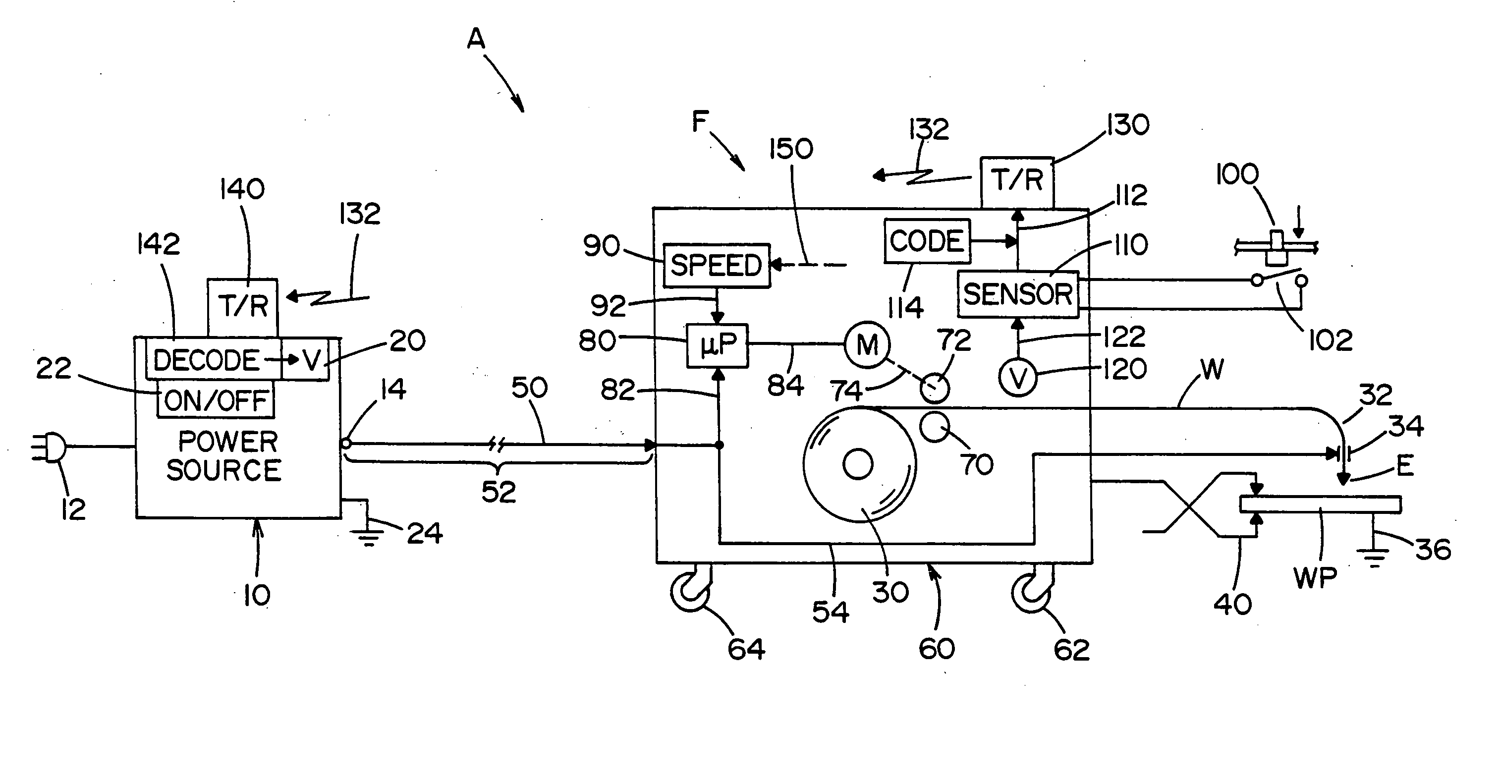
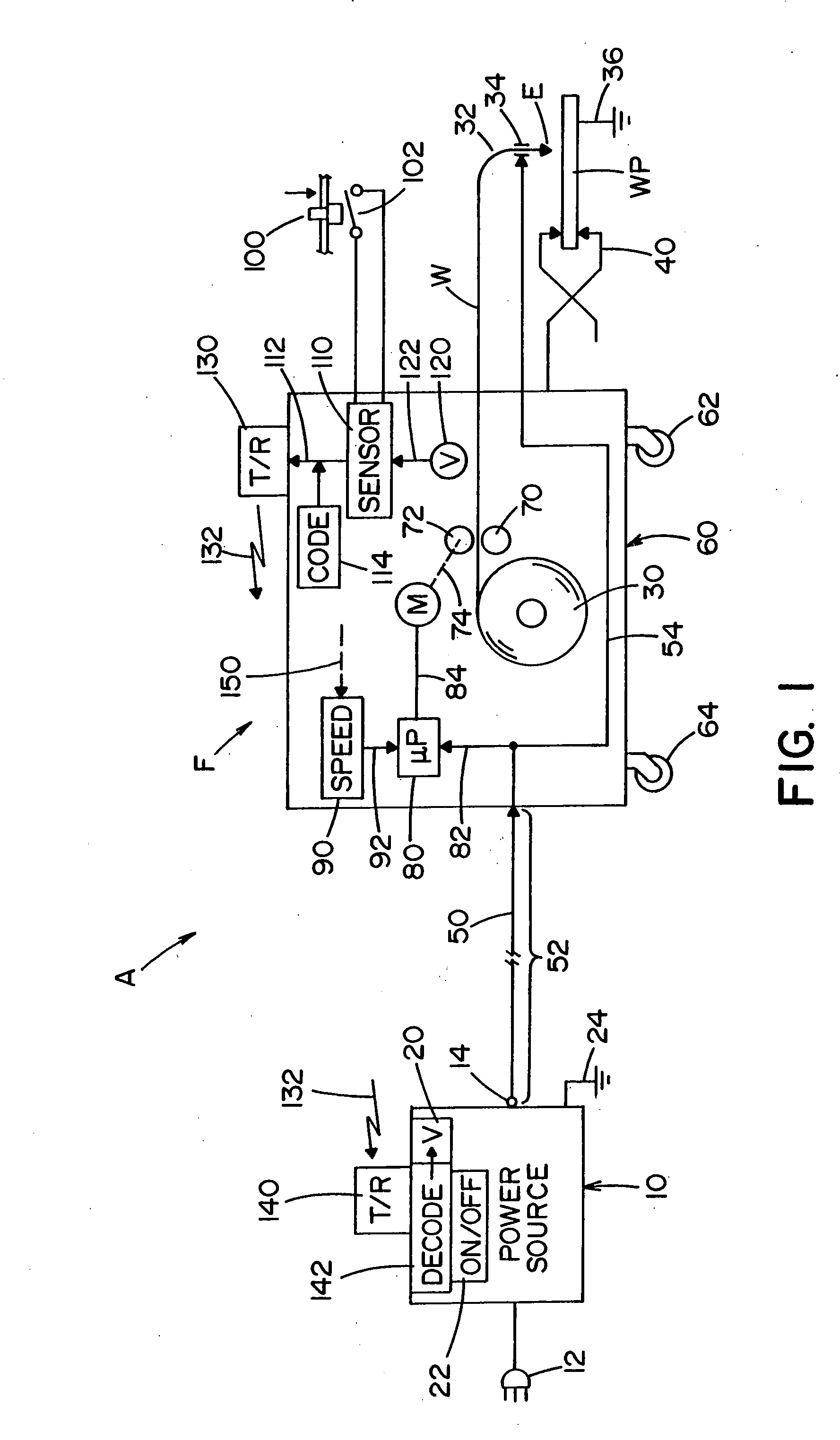
[0020] Referring now to the drawings, FIG. 1 shows an electric arc welder A of the type including a generally fixed power source and having input 12 and output terminal or output 14 wherein the arc voltage is controlled by a circuit when the power supply is on at switch 22. In accordance with normal practice, power source 10 has ground 24. This power source is to be controlled by signals from wire feeder F to control the operation of the power source and to remove the need for an internal mechanical connector in the wire feeder. This later feature will be discussed first.

[0021] The invention involves a remotely located wire feeder F of the type including an internal spool 30 for electric arc welding wire W. The wire is pulled from spool 30 and pushed through gun or torch 32 to a contact sleeve 34. Electric power is directed to electrode E, which is wire W, for performing an electric arc welding process between the electrode and workpiece WP. Standard ground 36 is connected to the w...


PUM

PropertyMeasurementUnit
voltageaaaaaaaaaa
welding currentaaaaaaaaaa
arc voltageaaaaaaaaaa

Abstract

A wire feeder including a motor driving a set of feed rolls to force a welding wire from a spool through a welding torch to a welding operation. The wire feeder has an input lead to be connected to the output lead of one of a plurality of remotely located power sources, each having a signal receiver for receiving transmitted signal with a code unique to one of the power sources. The receiver having an output for controlling a parameter or condition of the one power source in accordance with a received signal with the unique code. A transmitter on each of said plurality of power sources for transmitting on its output lead a coded signal specific to the power source. A signal receiver on said wire feeder to receive a unique code from the specific power source actually connected to the wire feeder and a circuit on the wire feeder for transmitting command signals from the wire feeder, which command signals each have the unique code specific to the power source connected to said wire feeder.

Description

[0001] The present invention relates to the art of electric arc welding and more particularly to a wire feeder with remote control for directing power to the feeder and to the arc. BACKGROUND OF INVENTION [0002] In many welding applications, a power source is in a fixed location and provides arc power through an electrode cable to a remotely located wire feeder having a spool of welding wire driven by a pair of feed rolls through an elongated tube out a welding torch to the welding operation. Current is directed through the electrode cable to the remotely located wire feeder that is movable from position to position for accommodating welding at different locations. The power on the electrode cable drives the motor that rotates feed rolls for pulling wire from the spool and forcing it through the gun or torch. A trigger on the gun or torch closes a switch to initiate the welding operation and start the drive motor for feeding wire. In accordance with this technology, the electrode ca...

Claims


Application Information

Patent Timeline
Patent Type & Authority Applications(United States)
IPC IPC(8): B23K9/10
CPCB23K9/095B23K9/10B23K9/133B23K9/124B23K9/1087
Inventor FURMAN, EDWARD M.CLARK, KEITH L.
Owner LINCOLN GLOBAL INC
Why Eureka
Try Eureka