Electric arc welding system

a welding system and arc welding technology, applied in welding apparatus, electric heating, manufacturing tools, etc., can solve the problems of not being suitable for central control by the internet and/or local area network control, requiring accurate current balance, and requiring a single high-capacity output switching network. achieve the effect of preventing or reducing electrode interference, high capacity and increasing current demands

Inactive Publication Date: 2002-10-29
LINCOLN GLOBAL INC
View PDF4 Cites 148 Cited by
  • Summary
  • Abstract
  • Description
  • Claims
  • Application Information

AI Technical Summary

Benefits of technology

Another object of the present invention is the provision of the arc welding cell or system, as defined above, which cell or system can be used for driving two or more tandem mounted electrodes with offset phase relationship to prevent or reduce electrode interference.
Still a further object of the present invention is the provision of an arc welding cell or system, as defined above, which cell or system utilizes a series of smaller power supplies that are combinable to create a high capacity welding power supply for a single electrode. In this manner, several small power supplies can be combined to produce larger power supplies as greater current demands are experienced.
Still another object of the present invention is the provision of an arc welding cell or system, as defined above, which cell or system allows control of one power supply in the cell by parameters different from any other power supply. In this manner, one power supply can be maintained at a higher level while the other power supplies have a greater range for responding to larger current demands.

Problems solved by technology

The disadvantage has been that such systems required the current to be accurately balanced and required a single high capacity output switching network.
Such systems were not suitable for central control by the internet and / or local area network control because an elaborate network to merely provide offset between cells was not advantageous.

Method used


Image

  • Electric arc welding system
  • Electric arc welding system
  • Electric arc welding system

Examples


Embodiment Construction

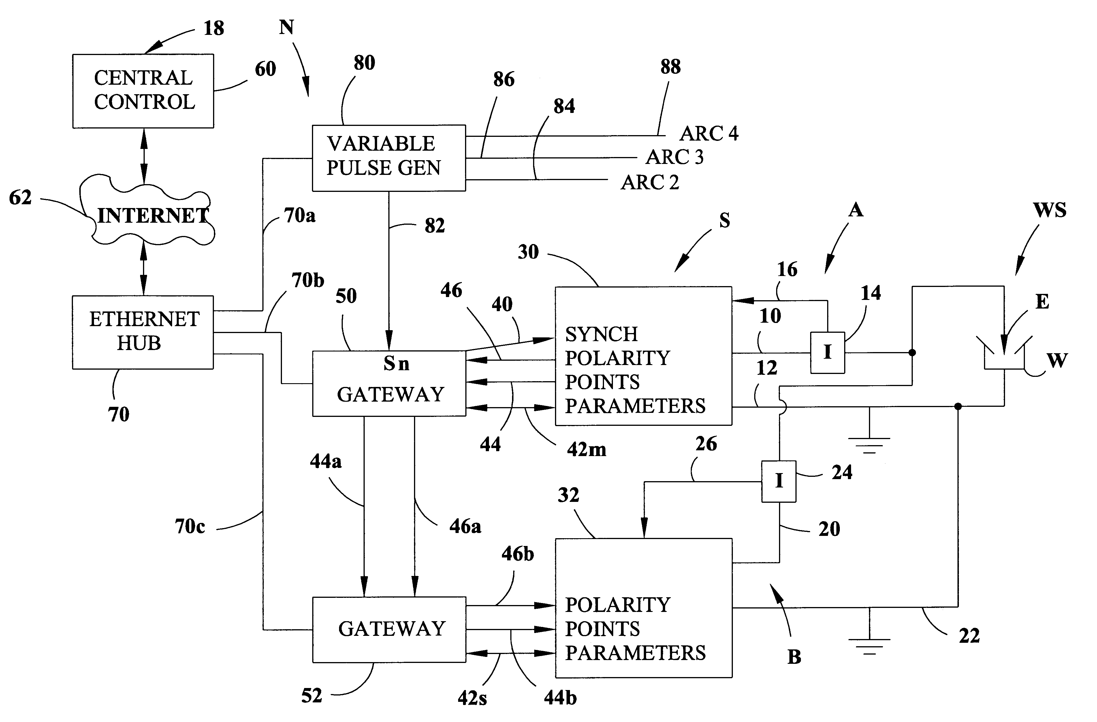
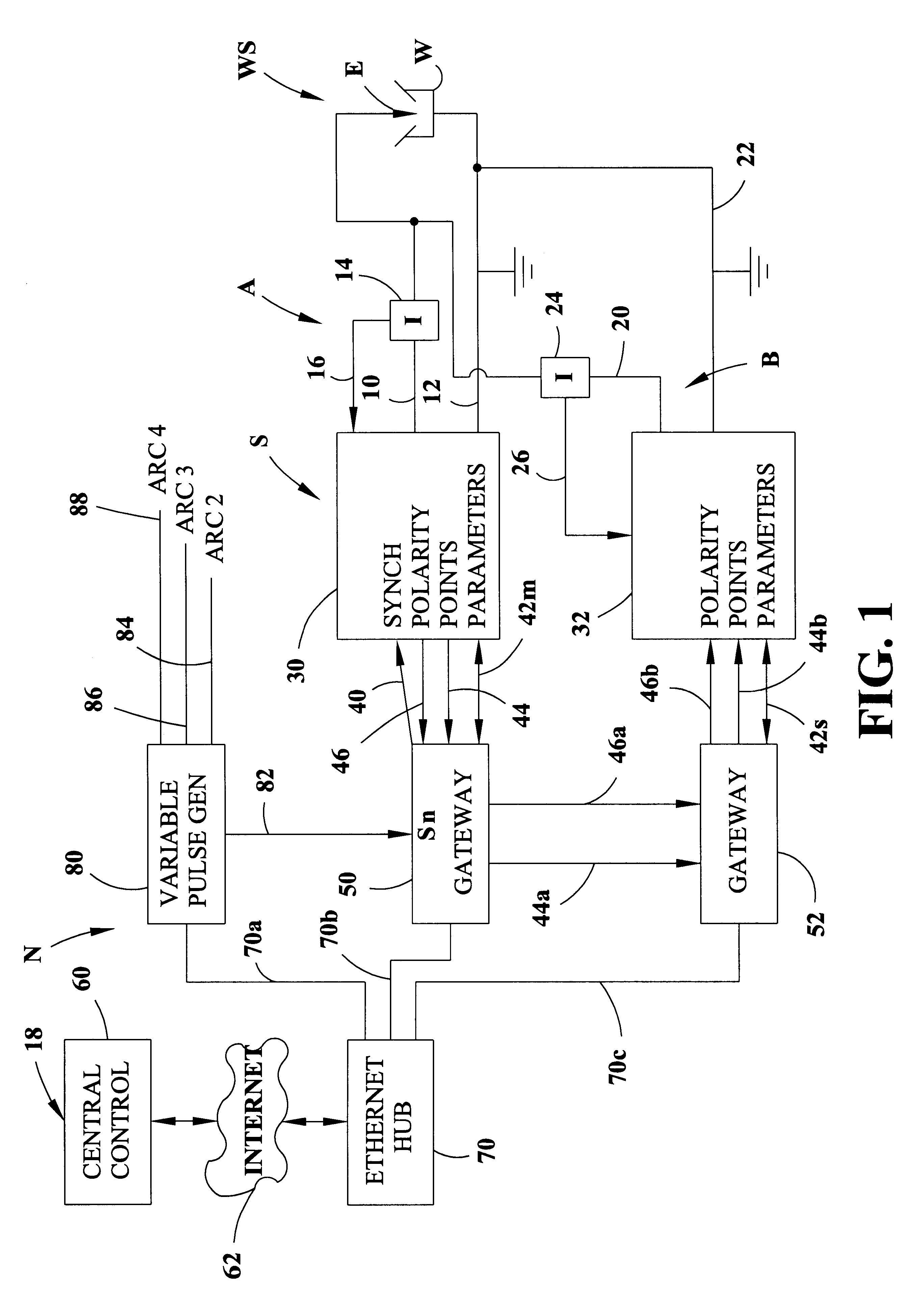
Referring now to the drawings wherein the showings are for the purpose of illustrating a preferred embodiment of the invention only and not for the purpose of limiting same, in FIG. 1 there is a single electric arc welding system S in the form of a single cell to create an alternating current as an arc at weld station WS. This system or cell includes a first master welder A with output leads 10, 12 in series with electrode E and workpiece W in the form of a pipe seam joint or other welding operation. Hall effect current transducer 14 provides a voltage in line 16 proportional to the current of welder A. Less time critical data, such as welding parameters, are generated at a remote central control 18. In a like manner, a slave following welder B includes leads 20, 22 connected in parallel with leads 10, 12 to direct an additional AC current to the weld station WS. Hall effect current transducer 24 creates a voltage in line 26 representing current levels in welder B during the welding...


PUM

PropertyMeasurementUnit
time accuracyaaaaaaaaaa
currentaaaaaaaaaa
timeaaaaaaaaaa

Abstract

An electric arc welding system for creating an AC welding arc between an electrode and a workpiece wherein the system comprises a first controller for a first power supply to cause the first power supply to create an AC current between the electrode and workpiece by generating a switch signal or command with polarity reversing switching points in the first controller, with the first controller operated at first welding parameters in response to first power supply specific parameter signals to the first controller. The system has at least one slave controller for operating a slave power supply to create an AC current between the electrode and workpiece by reversing polarity of the AC current at switching points where the slave controller is operated at second welding parameters in response to second power supply specific parameter signals to the slave controller. An information network connected to the first controller and the slave controller and containing digital first and second power supply specific parameter signals for the first controller and the slave controller and a digital interface connects the first controller with the slave controller to control the switching points of said second power supply by the switch signal or command from the first controller.

Description

The present invention relates to the art of electric arc welding and more particularly to an electric arc welding system for combining power supplies to operate tandem electrodes.INCORPORATION BY REFERENCEThe present invention is directed to an electric arc welding system utilizing high capacity alternating circuit power supplies for driving two or more tandem electrodes of the type used in seam welding of large metal blanks. Although the invention can be used with any standard AC power supply with switches for changing the output polarity, it is preferred that the power supplies use the switching concept disclosed in Stava U.S. Pat. No. 6,111,216 wherein the power supply is an inverter having two large output polarity switches with the arc current being reduced before the switches reverse the polarity. Consequently, the term "switching point" is a complex procedure whereby the power supply is first turned off awaiting a current less than a preselected value, such as 100 amperes. Up...

Claims


Application Information

Patent Timeline
Patent Type & Authority Patents(United States)
IPC IPC(8): B23K9/10B23K9/095
CPCB23K9/0953B23K9/0956B23K9/1062B23K9/1075B23K9/10
Inventor HOUSTON, WILLIAM S.MYERS, RUSSELL K.STAVA, ELLIOTT K.
Owner LINCOLN GLOBAL INC
Why Eureka
Try Eureka