Embolic filters with controlled pore size

a filter and pore size technology, applied in the field of emboli and particulate capture devices, can solve the problems of compromising the flow of blood at a location removed from the treatment site, affecting the flow of blood, and affecting the design of filters with appropriate characteristics, etc., to achieve controllable pore size, high embolic capacity, and high percentage of pore area

Active Publication Date: 2008-01-29
COVIDIEN LP
View PDF89 Cites 234 Cited by
  • Summary
  • Abstract
  • Description
  • Claims
  • Application Information

AI Technical Summary

Benefits of technology

[0007]The invention provides an embolic filter that is designed to provide the desired characteristics of controlled pore size, high percentage of pore area, high embolic capacity, patency, mechanical strength, low collapsed or retracted profile, and strength during recovery.

Problems solved by technology

During vascular surgery or endovascular treatment of vessels including thrombectomy, atherectomy, balloon angioplasty, and / or stent deployment, debris such as plaque and blood clots can move from the treatment site through a vein or artery and compromise the flow of blood at a location removed from the treatment site.
This uncertainty adds to the complexity of designing a filter with the appropriate characteristics.
Small particles might pass through the filter pores and lodge downstream in tissues where they may cause tissue ischemia or tissue necrosis.
However, in the brain there is no easy and inexpensive method to evaluate the effect of a shower of emboli.
For example, a 100 micron particle may lodge in a part of the brain where few adverse consequences are detected clinically, or it can lodge in a retinal artery, resulting in blindness in one eye.
It is difficult to make an embolic protection filter with the appropriate combination of pore size, pore area, embolic capacity, patency, mechanical strength, low collapsed or retracted profile, and recovery characteristics.
Embolic filters made from polymer films commonly have a narrow range of pore sizes but suffer from a low percent open area because there is a limit to how closely the holes can be placed.
Too little spacing between holes can result in a weak film that tears upon filter recovery.
Foams tend to be bulky, thereby compromising the collapsed profile, and they have low strength.
A wide range of pore sizes is undesirable for a number of reasons.

Method used


Image

  • Embolic filters with controlled pore size
  • Embolic filters with controlled pore size
  • Embolic filters with controlled pore size

Examples


Embodiment Construction

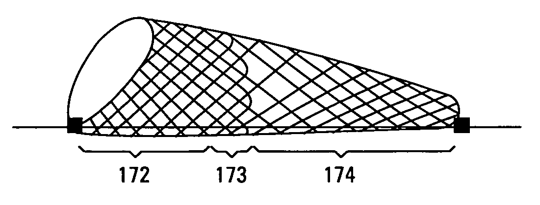
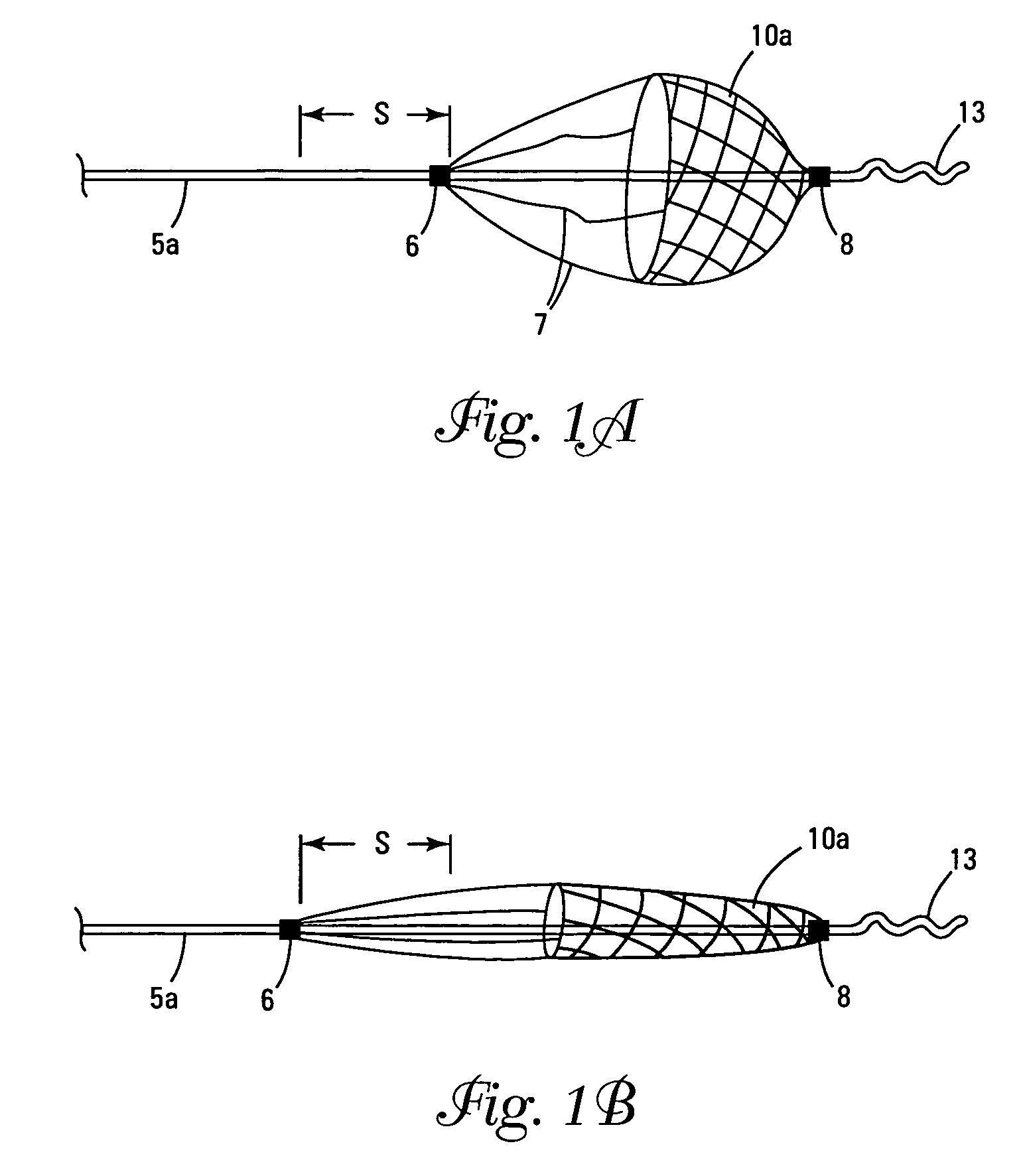
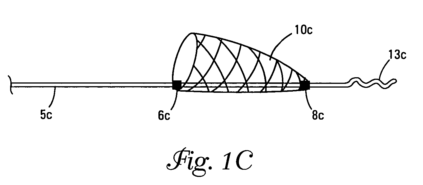
[0027]The terms “distal” and “proximal” as used herein refer to the relative position of the guidewire, catheters, and filter in a lumen. Thus, “proximal” refers to a location upstream from the “distal” position. That is, the flow of a body fluid, such as blood, moves from the proximal to the distal portions of the device.

[0028]The invention encompasses the use of any filtration device to be deployed in a lumen or vessel of a patient Although the examples relate generally to filter protection devices deployed distal to a treatment site, the device can also be deployed proximal to a treatment site in connection with interrupting or reversing flow through the vessel. In the case of a proximally deployed device, it will be advantageous to construct the device on a hollow elongate member so as to preserve access to the treatment site through the hollow member.

[0029]In a preferred embodiment, the distal protection system comprises a catheter which is loaded with an elongate support membe...


PUM

PropertyMeasurementUnit
pore sizeaaaaaaaaaa
pore sizeaaaaaaaaaa
pore sizeaaaaaaaaaa

Abstract

The invention provides a device for filtering emboli from blood flowing through a lumen defined by the walls of a vessel in a patient's body comprising a filter element. The filter is expandable from a collapsed configuration when the filter element is restrained to an expanded configuration when the filter element is unrestrained, and the filter element comprises a self-expanding material having pores. When the filter element is in the expanded configuration, the average pore size is from 30 to 300 microns and the standard deviation of the pore size is less than 20 percent of the average pore size.

Description

FIELD OF THE INVENTION[0001]This invention relates to devices used in a blood vessel or other lumen in a patient's body. In particular, the present invention relates to devices for capturing emboli and particulate in a lumen.BACKGROUND OF THE INVENTION[0002]During vascular surgery or endovascular treatment of vessels including thrombectomy, atherectomy, balloon angioplasty, and / or stent deployment, debris such as plaque and blood clots can move from the treatment site through a vein or artery and compromise the flow of blood at a location removed from the treatment site. In particular, various protection systems have been developed to prevent such debris from embolizing in the vessel. Distal protection devices include filters and occlusive devices (e.g., balloons) placed distally of the treatment site. Proximal protection devices include filters and occlusive devices placed proximally of the treatment site. In the case of filters, emboli collect within or on the filter. The filter w...

Claims


Application Information

Patent Timeline
Patent Type & Authority Patents(United States)
IPC IPC(8): A61M29/00A61F2/01
CPCA61F2/01D04B1/16D04C1/02D04C3/48A61F2/013D10B2509/06A61F2002/018A61F2230/0006A61F2230/0008A61F2230/0067A61F2230/0069A61F2230/008A61F2/0105A61F2/0108
Inventor CLUBB, THOMAS L.KUSLEIKA, RICHARD S.ANDERSON, KENT D.BERRADA, MARWANE S.
Owner COVIDIEN LP
Why Eureka
Try Eureka