

Lithium metal dispersion in electrodes
a technology of lithium metal and electrodes, applied in the field of secondary batteries, can solve the problems of limiting the choice of cathode active materials, raising safety concerns, and unsafe conditions in the battery, and achieves the effects of improving operational safety, high specific capacity, and good cycleability
- Summary
- Abstract
- Description
- Claims
- Application Information
AI Technical Summary
Benefits of technology
Problems solved by technology
Method used
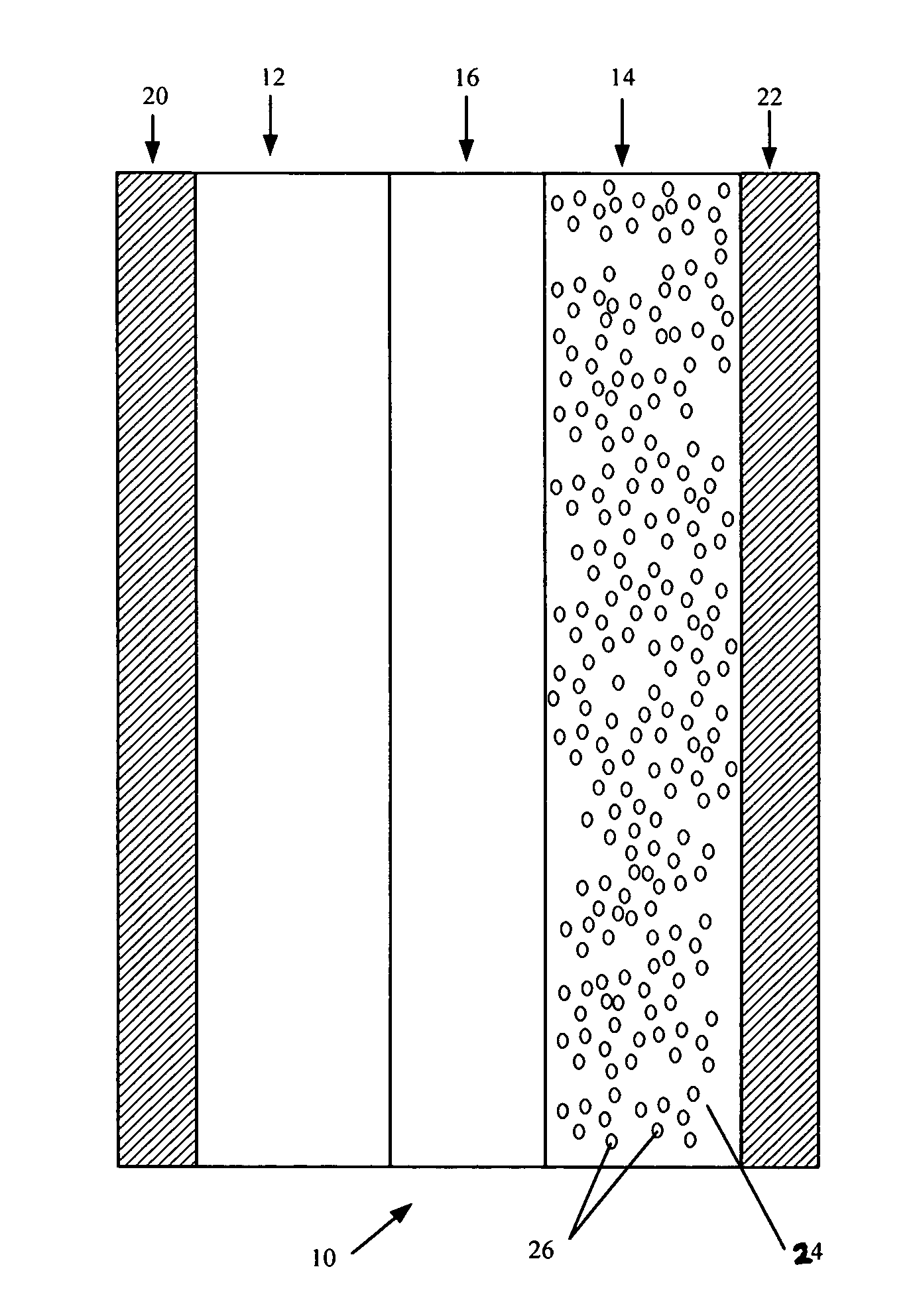
Image

Examples
example 1
Ethylene Propylene Diene Terpolymer and Cyclohexane
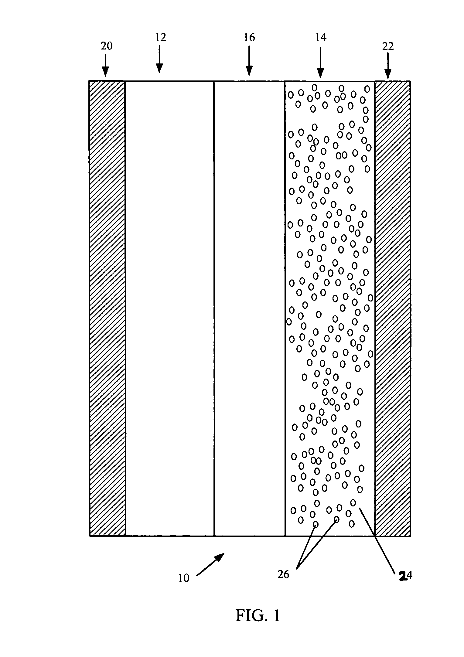
[0074] A coating solution containing cyclohexane, lithium powder and ethylene propylene diene terpolymer (Nordel® IP 4570) was tested for thermal stability over the temperature range of interest. The solution consisted of 8.8 ml of cyclohexane, 0.24 g of lithium powder, and 0.127 g of ethylene propylene diene terpolymer. A Reactive System Screening Tool was used as the calorimeter of choice. During the test, the pressure inside the chamber was set at 200 psig using argon to enable testing of the system beyond the boiling point of cyclohexane. No self-heating was detected over a temperature range of 19° C. to 94° C. A plot of the test is illustrated in FIG. 2. The boiling point of cyclohexane is 80.7° C. at 1 atm, so scanning above that temperature was not necessary and the test was stopped at 94° C. As illustrated in FIG. 2, the instrument maintained a steady heat rate of 0.5° C. per minute during the ramp. If self-heating had been...
example 2
[0075] Lithium powder, in an amount of 0.531 g, was mixed with 8 ml of p-xylene and a thermal stability test was conducted using the Reactive System Screening Tool described in Example 1. The test was conducted between room temperature and 180° C. No self-heating was detected over this temperature range, indicating that lithium powder is stable in p-xylene between room temperature and 180° C.
example 3
Dimethyl Propylene Urea and Lithium Powder
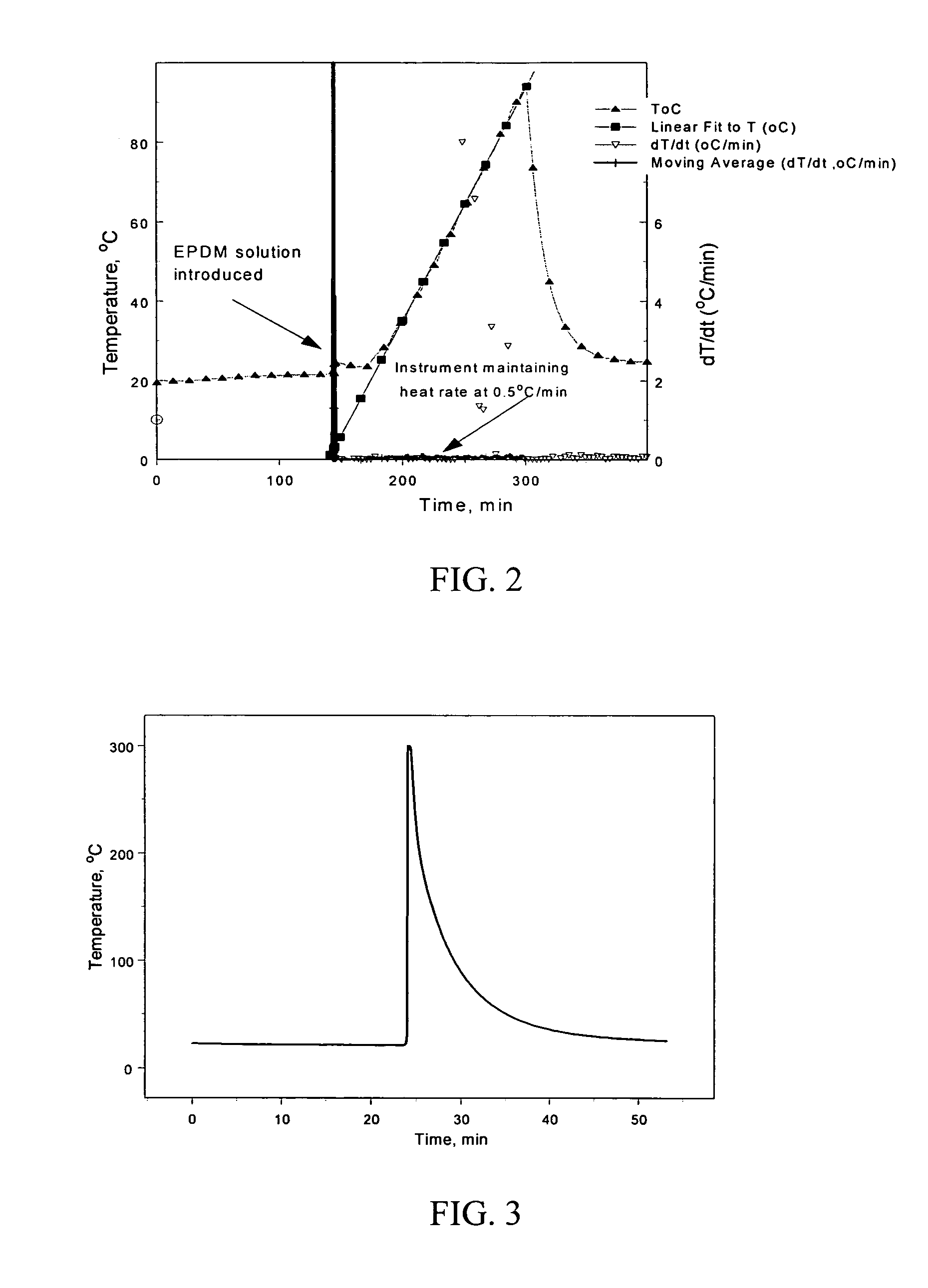
[0076] A solution containing dimethyl propylene urea and lithium powder was tested for thermal stability using Reactive System Screening Tool techniques with the same set-up and procedure as described in Example 1. Self-heating was detected within 3 seconds of the addition of dimethyl propylene urea to the lithium powder at a temperature of 25° C. The self-heating increased at a rate of over 1000° C. per minute. FIG. 3 illustrates the thermal run away of the test. The presence of self-heating in the system indicates that the dimethyl propylene urea is not a suitable solvent for forming the anodes of the present invention because it reacts with lithium powder.
[0077] In an alternative anode 14 production process, the lithium metal can be provided in the anode 14 by immersing the host material 24 in a suspension containing lithium metal in a non-aqueous liquid such a hydrocarbon solvent (e.g. hexane). The lithium metal 26 used in the suspensi...
PUM
 Abstract
Description
Claims
Application Information