Method and system for starting a sensorless motor

a sensorless motor and motor technology, applied in the direction of motor/generator/converter stoppers, dynamo-electric converter control, multiple dynamo-motor starters, etc., can solve the problem of current phase and magnitude of the back emf, etc., to prevent overcurrent shutdown of the inverter and large motor current

Active Publication Date: 2007-01-04
INFINEON TECH AMERICAS CORP
View PDF14 Cites 149 Cited by
  • Summary
  • Abstract
  • Description
  • Claims
  • Application Information

AI Technical Summary

Benefits of technology

[0009] According to an embodiment of the invention, a motor drive system for driving a sensorless motor includes a controller and an inverter, the controller including a catch start sequencer for controlling the motor drive system to robustly start the motor in the event the motor rotor is initially rotating due to an external torquing force. Specifically, according to an embodiment of the invention, upon initial energizing of the inverter, the catch start sequencer assumes that the motor rotor may be already rotating and causes the motor drive system to track the rotor position and to enforce zero current regulation, resulting in the phase and magnitude of the inverter output voltage matching the phase and magnitude of the motor back EMF. As a result, a large motor current is prevented at the initial start of the inverter, thereby preventing over current shutdown of the inverter.
[0012] Assuming, however, that the catch start sequencer detects reverse rotor rotation, the catch start sequencer next proceeds to slow down and possibly stop the reverse rotation of the rotor. Specifically, according to an embodiment of the invention, the catch start sequencer causes the inverter to apply a zero voltage vector to the motor, the zero voltage vector shorting the motor phase windings and thereby having the effect of slowing down the rotational spin of the rotor and possibly stopping the rotor.
[0015] According to an embodiment of the invention, the catch start sequencer continues to apply the open loop forward rotating current vector until the rotor's forward speed exceeds a threshold. Thereafter, the catch start sequencer causes the motor drive system to switch to closed loop control and completes operation by configuring the motor drive system to bring the speed of the motor up to a set point and to assume normal operation.

Problems solved by technology

These motor drive systems and motors are sensorless in that they do not include functionality to measure the voltage feedback from the motor and / or sensors to detect the position of the motor rotor.
Because the motor drive system and motor are sensorless, however, the phase and magnitude of this back EMF are unknown to the motor drive system when activating the inverter.
Problematically, if the motor is spinning at high enough rate and thereby generating a large back EMF, this mismatch can result in a large motor current, thereby causing over current shutdown of the inverter.
An additional problem also occurs when the rotor has reverse rotation prior to activating the inverter.
Under these conditions, the sensorless (i.e., no voltage or Hall sensors, only current sensors) motor drive system must control the motor speed to go from the reverse direction to the forward direction, which may be difficult when the inverter has no regeneration capability and the rotor is spinning at a high rate.

Method used


Image

  • Method and system for starting a sensorless motor
  • Method and system for starting a sensorless motor
  • Method and system for starting a sensorless motor

Examples


Embodiment Construction

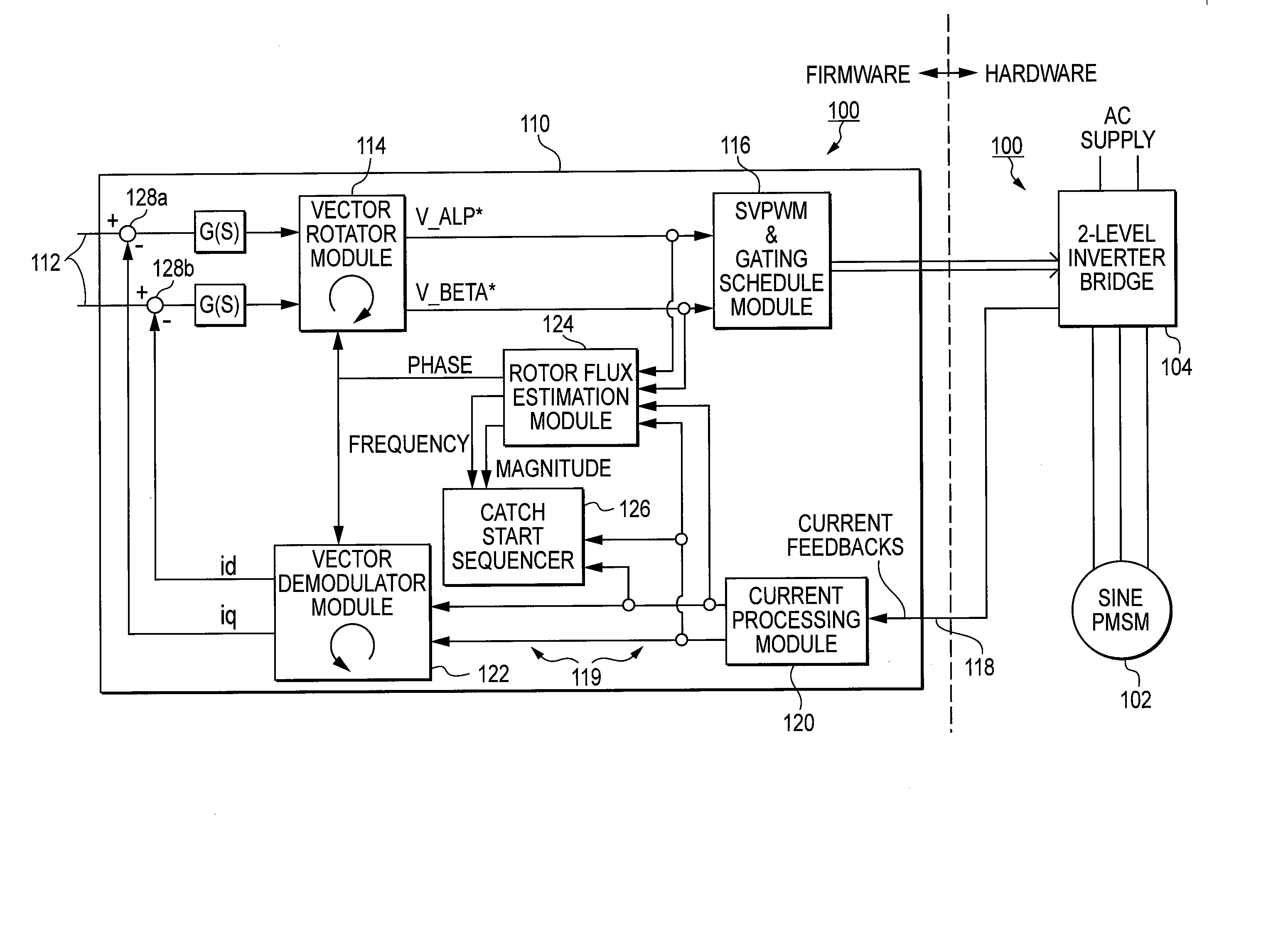
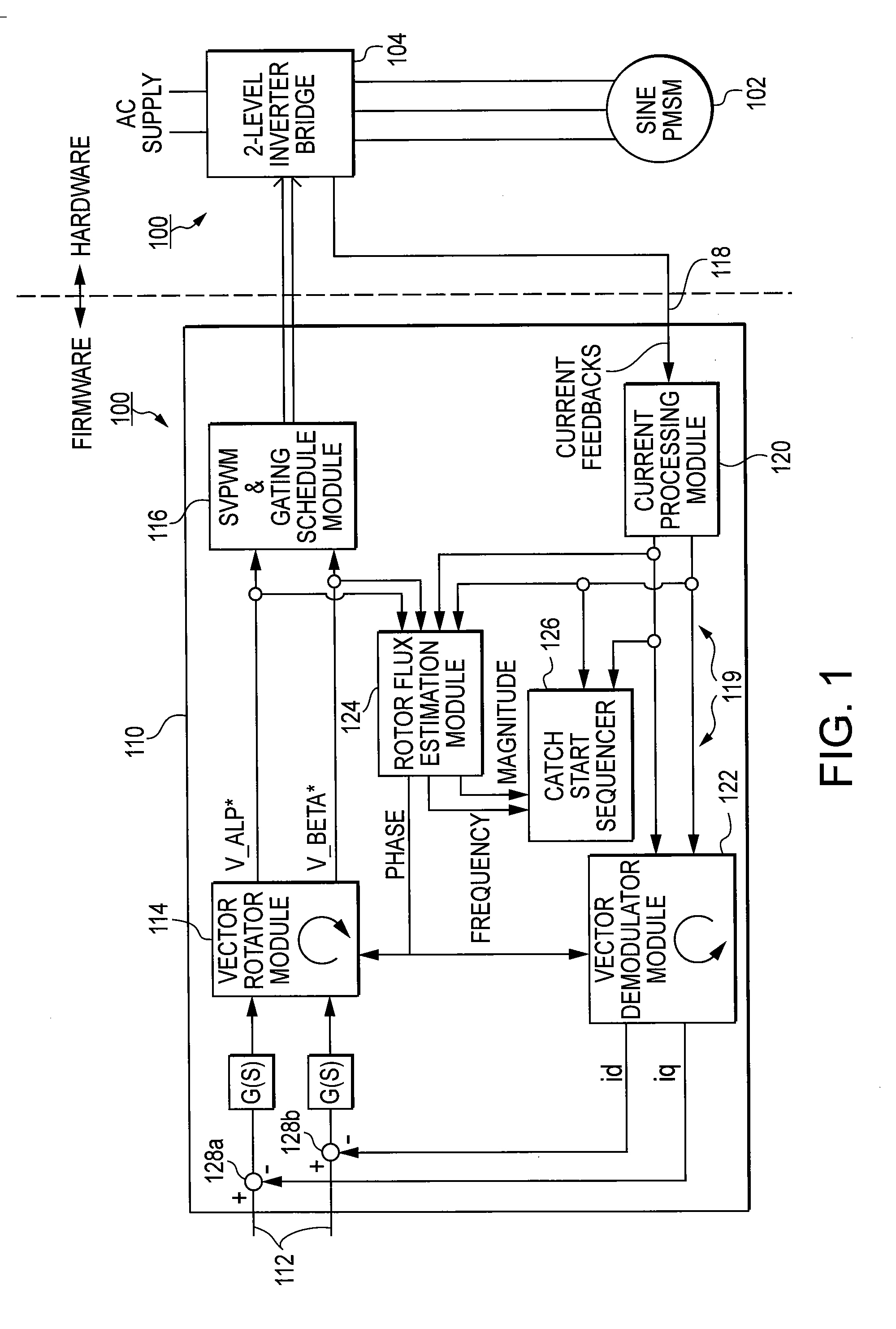
[0028] Referring to FIG. 1, there is shown a functional diagram of a motor drive system 100 according to an embodiment of the invention for driving a sensorless motor 102, such as a three-phase permanent magnet synchronous motor (PMSM). Motor drive system 100 includes an inverter 104, such as a three-phase inverter, that generates power signals that drive motor 102, and includes a controller 110 for configuring the switches of inverter 104 in order to generate the motor power signals. Controller 110 includes control inputs 112 for receiving motor speed commands, a vector rotator module 114, a pulse width modulation module 116, a rotor flux estimation module 124, and a d-q current regulator 119 configured as a current feedback loop between inverter 104 and control inputs 112. As shown, d-q current regulator 119 includes feedback lines 118 interfaced to inverter 104 and for obtaining representations of the three motor phase currents of motor 102, a current processing module 120 interf...


PUM


Abstract

A motor drive system for a sensorless motor includes a catch start sequencer that controls the motor drive system to robustly start the motor in the event the motor rotor is rotating in forward or reverse direction prior to activating the motor drive system. In particular, the catch start sequencer causes the motor drive system to initially find and track the rotor position, and then determines the speed and possibly the direction of rotation of the rotor. If the rotor is rotating in the reverse direction, the catch start sequencer controls the motor drive system to slow the speed of rotation and to then start the rotor rotating in the forward direction.

Description

RELATED APPLICATIONS [0001] This application is based on and claims priority to U.S. Provisional Application No. 60 / 696,194, filed on Jul. 1, 2005, by Eddy Ying Yin Ho, entitled, “REVERSE CATCH SPIN CONTROL FOR FAN MOTORS,” and is based on and claims priority to U.S. Provisional Application No. 60 / 717,103, filed on Sep. 14, 2005, by Eddy Ying Yin Ho, entitled, “CATCH START OF PERMANENT MAGNET MOTORS WITHOUT VOLTAGE OR SHAFT POSITION SENSORS,” the contents of which applications are herein incorporated by reference.BACKGROUND OF THE INVENTION [0002] 1. Field of the Invention [0003] This invention relates to a motor drive system and more specifically, relates to a motor drive system for starting a sensorless motor where the motor rotor may be rotating prior to activation of the motor drive system. [0004] 2. Description of the Art [0005] Many motor drive systems and motors, such as permanent magnet synchronous motors (PMSM), use sensorless control techniques to reduce cost and to increa...

Claims


Application Information

Patent Timeline
Patent Type & Authority Applications(United States)
IPC IPC(8): H02P1/18
CPCH02P1/029H02P3/22F04D27/004H02P21/145H02P21/0032F05D2260/85H02P21/16H02P21/34Y02B30/70H02P1/16H02P21/00
Inventor HO, EDDY YING YIN
Owner INFINEON TECH AMERICAS CORP
Why Eureka
Try Eureka