Method and device for producing three-dimensional objects

a three-dimensional object and three-dimensional technology, applied in auxillary shaping apparatus, manufacturing tools, additive manufacturing processes, etc., can solve the problems of difficult control, poor structure of powder layer, and large temperature gradient, and increase the electrical conductivity of powder. , the effect of high beam curren

Active Publication Date: 2012-05-29
ARCAM AB
View PDF12 Cites 145 Cited by
  • Summary
  • Abstract
  • Description
  • Claims
  • Application Information

AI Technical Summary

Benefits of technology

[0015]An advantage of the present invention is that the pre-heating step allows the powder layer to be homogenously heated so as to avoid having too large a temperature gradient in the interface between melted metal and powder in the subsequent solidifying step. By using a security distance adapted to prevent summation effects from consecutively scanned paths, it is possible to prevent the energy deposited to the powder during scanning of a first path adding to the energy deposited during scan of a second path scanned directly after the first path. Thus, large temperature gradients can also be avoided during the pre-heating stage.
[0016]When using an electron beam the pre-heating has a further advantageous effect in that it increases the electrical conductivity of the powder. This, in turn, has the effect that a high beam current can be used in the subsequent solidifying step. Also, the security distance has an additional advantage when using an electron beam in that it eliminates the risk of forming too large a charge density in the relatively cool powder during the pre-heating step. Thus, powder discharge is prevented.
[0017]The inventive use of the beam for pre-heating the powder has several advantages compared to the rather obvious alternative to heat up an entire powder bed using e.g. heating elements. One advantage is that no further heating equipment is needed. Another advantage is that only the part of the powder bed that really needs to be heated, i.e. a fraction of the upper layer of the powder bed, is actually heated. This makes the process very efficient.
[0018]In a first advantageous embodiment of the method of the present invention the pre-heating step further comprises the sub-step of re-scanning the pre-heating powder layer area. In this manner, the pre-heating area can be gradually and homogeneously heated up. Preferably, the paths followed during a re-scan of the pre-heating powder layer area are displaced an interspacing distance in relation to the paths followed during a previous scan of the pre-heating powder layer area, wherein the interspacing distance is less than the minimum security distance. In this manner, it is possible to obtain a homogeneously pre-heated powder layer area in situations where it is necessary to use a scanning pattern where the paths are physically separated by a distance that is shorter than the minimum security distance, i.e. in situations where additional, more closely positioned paths are needed.
[0019]In a second advantageous embodiment of the inventive method of the present invention, the power of the beam is increased during the pre-heating step. This has the advantage that the beam power initially can be kept at a sufficiently low level to avoid large charge densities and / or temperature gradients, but also that the beam power increases so as the temperature of the powder increases as to speed up the pre-heating process as much as possible. In a preferred variant of the method of the present invention, the power of the beam is increased stepwise between consecutive scans or re-scans of the pre-heating powder layer area. This makes it relatively easy to control the process and allows the powder pre-heating area to be heated in a uniform manner.
[0020]In a third advantageous embodiment of the method of the present invention, the beam is an electron beam wherein the beam power is increased by increasing the beam current.

Problems solved by technology

The result of such a discharge is that the structure of the powder layer will be destroyed.
Applying the method according to U.S. Patent Publication No. 2005 / 0186538 to a powder melting / sintering device equipped with an electron beam is likely to give a poor result since no measures are taken in that method to avoid such discharges.
Disadvantages of this solution are, however, that the solidifying process of such a powder mixture may be difficult to control and that the properties of the formed product may be affected in a negative way.

Method used


Image

  • Method and device for producing three-dimensional objects
  • Method and device for producing three-dimensional objects
  • Method and device for producing three-dimensional objects

Examples


Embodiment Construction

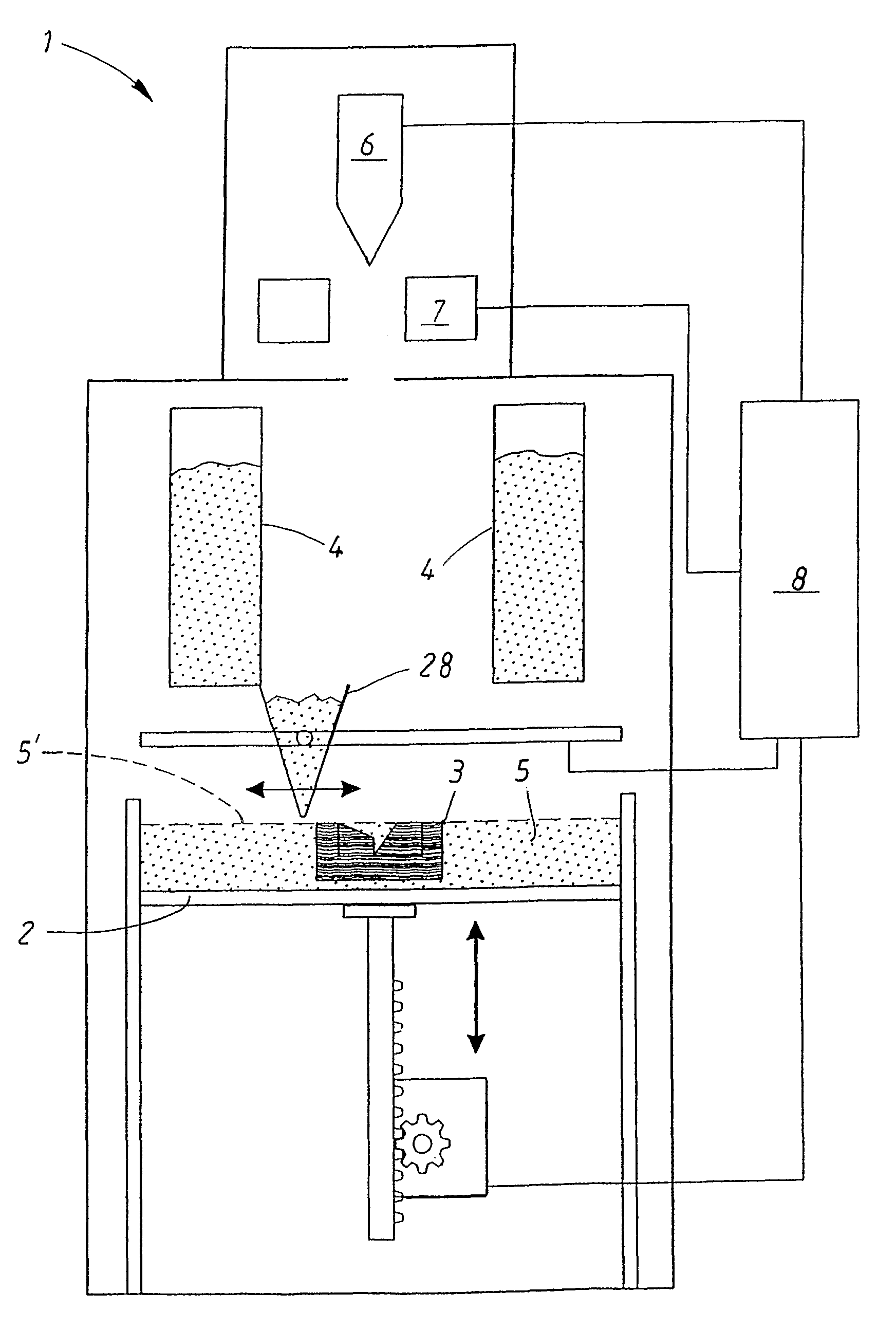
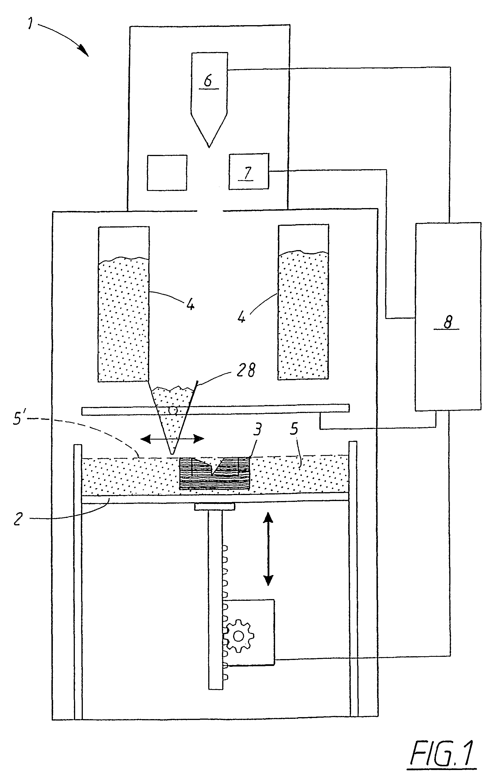
[0030]FIG. 1 shows an example of a known device 1 for producing a three-dimensional product. The device 1 comprises a vertically adjustable work table 2 on which a three-dimensional product 3 is to be built up, one or more powder dispensers 4, means 28 arranged to distribute a thin layer of powder on the work table 2 for forming a powder bed 5, a radiation gun 6 in the form of an electron gun for delivering energy to the powder bed 5 as to fuse together parts of the powder bed 5, deflection coils 7 for guiding the electron beam emitted by the radiation gun 6 over said work table 2, and a control unit 8 arranged to control the various parts of the device 1. In a typical work cycle, the work table 2 is lowered, a new layer of powder is applied onto the powder bed 5, and the electron beam is scanned over selected parts of the upper layer 5′ of the powder bed 5. In principal, this cycle is repeated until the product is finished. An expert in the field is familiar with the general functi...


PUM

PropertyMeasurementUnit
lengthaaaaaaaaaa
energyaaaaaaaaaa
interspacing distanceaaaaaaaaaa

Abstract

A method for producing three-dimensional objects from a powder material which is capable of solidification by irradiation with a high-energy beam is disclosed. The method comprises homogeneously pre-heating the powder material by scanning with the high-energy beam along predetermined paths over a pre-heating area so that consecutive paths are separated by a minimum security distance which is adapted to prevent undesirable summation effects in the pre-heating area, and then solidifying the powder material by fusing together the powder material. Apparatus for producing such three-dimensional objects is also disclosed.

Description

FIELD OF THE INVENTION[0001]The present invention relates to a method and apparatus for producing three-dimensional objects layer by layer using a powdery material which can be solidified by irradiating it with a high-energy beam. In particular, the present invention relates to a powder pre-heating process using an electron beam.BACKGROUND OF THE INVENTION[0002]Equipment for producing a three-dimensional object layer by layer using a powdery material which can be solidified, or fused together, by irradiating it with a high-energy beam of electromagnetic radiation or electrons are known from e.g. U.S. Pat. Nos. 4,863,538 and 5,647,931 and Swedish Patent No. 524,467. Such equipment includes for instance a supply of powder, means for applying a layer of powder on a vertically adjustable platform or working area, and means for directing the beam over the working area. The powder sinters or melts and solidifies as the beam moves over the working area.[0003]When melting or sintering a pow...

Claims


Application Information

Patent Timeline
Patent Type & Authority Patents(United States)
IPC IPC(8): H01J37/30
CPCB22F3/1055B29C67/0077B22F2999/00B22F3/1017B29C64/153Y02P10/25B22F10/28B22F10/366B22F10/362B22F10/37B22F3/105B29C67/00
Inventor LARSSON, MORGANSNIS, ANDERS
Owner ARCAM AB
Why Eureka
Try Eureka