Thermally driven knudsen pump

a knudsen pump, thermal drive technology, applied in the direction of positive displacement pump, piston pump, positive displacement liquid engine, etc., can solve the problem of increasing the gas flow impedance, and achieve the effect of improving thermal isolation, good thermal isolation, and maximizing thermal differen

Active Publication Date: 2012-08-16
UNIV OF LOUISVILLE RES FOUND INC
View PDF1 Cites 17 Cited by
  • Summary
  • Abstract
  • Description
  • Claims
  • Application Information

AI Technical Summary

Benefits of technology

[0024]One embodiment of the thermally driven pump of the present invention utilizes a thermoelectric material to assist with the thermal transpiration process resulting in a substantially symmetrical, bidirectional pump. A major challenge in the design of thermal transpiration based pumps is to ensure good thermal isolation between the hot and cold ends of the pump to maximize the thermal difference. The primary parameters affecting the thermal isolation are the thermal conductivity of the pump channel material and the length of the channel separating the hot and cold sides. Although a longer channel will improve the thermal isolation, a longer channel increases the gas flow impedance, requiring a tradeoff to be made.
[0030]The efficiency of a Knudsen pump is dependent on the ratio of the absolute temperatures. The greater the temperature gradient across the channel, the more efficient the pump. As compared to other Knudsen pumps, the thermoelectric pump of the present invention maintains a lower temperature on the cold end of the thermal transpiration channel and a higher temperature on the hot end of the channel thereby producing a greater temperature gradient resulting in increased efficiency. This active cooling of the cold end results in lower temperatures and a larger temperature gradient than those exhibited by prior art Knudsen pumps. Additionally, the design of the pump of the present invention eliminates the need for a heat sink and makes the pump geometry symmetrical, as compared to existing designs which are asymmetrical. Due to the symmetrical design of the pump of the present invention, the hot and cold ends of the pump can be interchanged by changing the polarity of the power supply thus creating a bi-directional pump.
[0031]A second embodiment of the thermally driven pump of the present invention comprises a uni-directional, pneumatic, micro fluidic, Knudsen pump which can be integrated into a lab-on-chip device. The micro fluidic pump is configured to pump liquids. The pump is integrated into the substrate of the lab-on-chip device during fabrication of the substrate while creating other channels and lab-on-chip components. The simultaneous fabrication of the Knudsen pump during fabrication of other lab-on-chip channels and components facilitates an integrated configuration between the Knudsen pump and the channels through which the pump is connected and may push liquids through during operation of the lab-on-chip device.

Problems solved by technology

A major challenge in the design of thermal transpiration based pumps is to ensure good thermal isolation between the hot and cold ends of the pump to maximize the thermal difference.
Although a longer channel will improve the thermal isolation, a longer channel increases the gas flow impedance, requiring a tradeoff to be made.

Method used


Image

  • Thermally driven knudsen pump
  • Thermally driven knudsen pump
  • Thermally driven knudsen pump

Examples


first embodiment

Examples of the First Embodiment

[0075]Other features of the first embodiment of the present invention will become apparent in the course of the following examples which are given for illustration of the invention and are not intended to be limiting thereof.

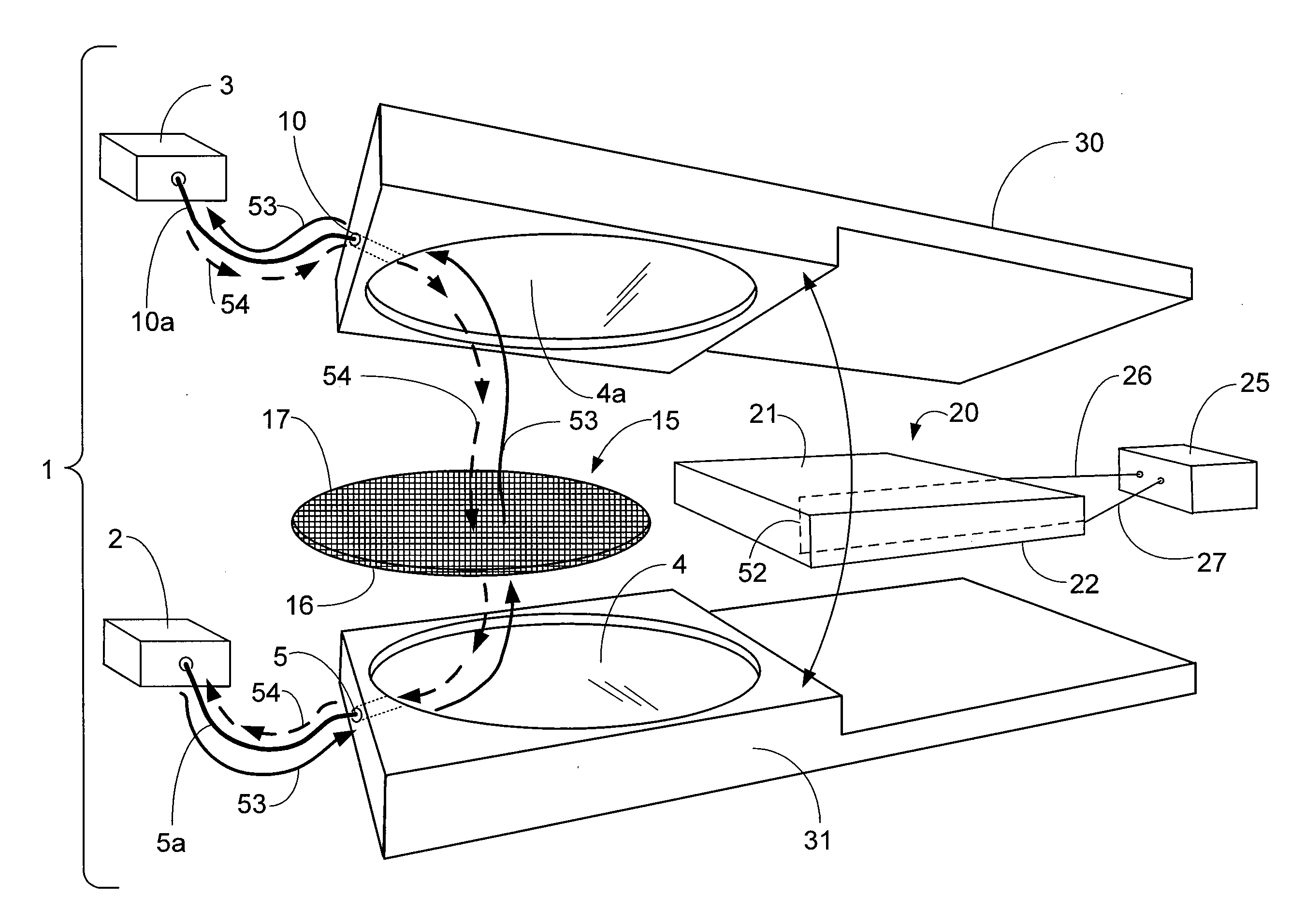
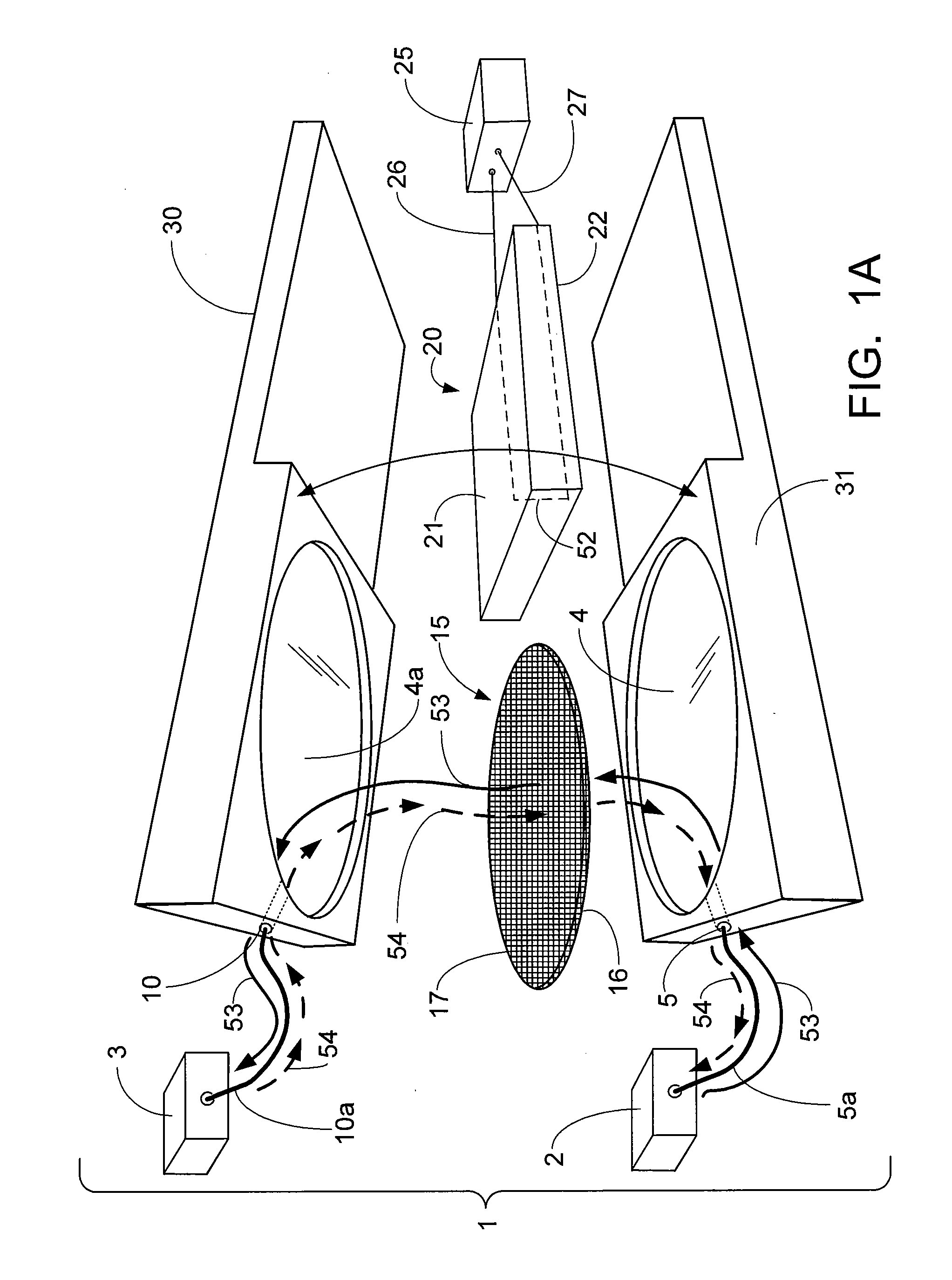
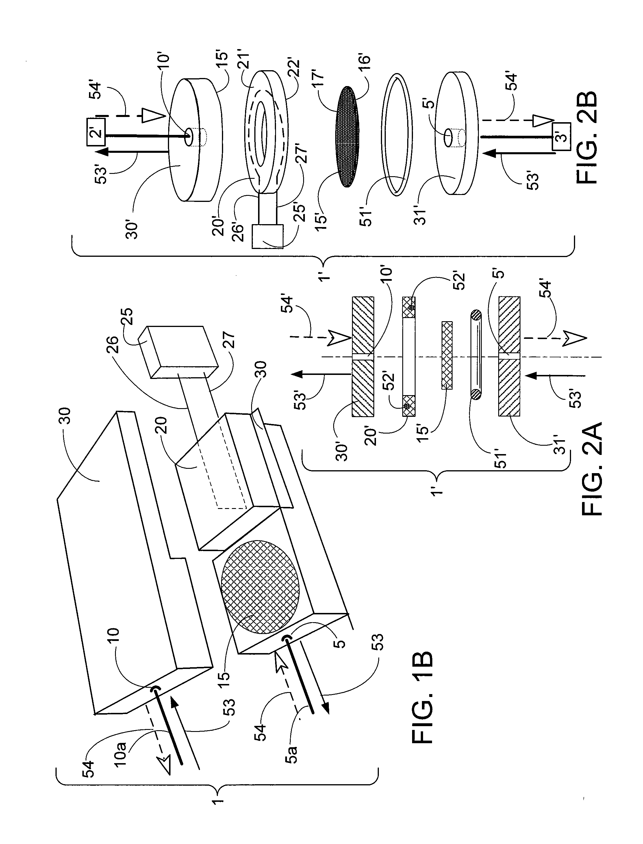
[0076]One example of the lateral pump design comprises a nanoporous article made of a nanoporous polymer material having nanochannels for the thermoelectric Knudsen pump. This design provides a high flow rate due to parallel nanochannels acting in unison. Fifty nanometer (50 nm) pore sized filter disc composed of mixed cellulose esters from Millipore Corporation, USA, was used for thermal transpiration channels. For a 50 nm pore size channel over a temperature rage of between approximately 280° K to 380° K, the Kn is between about 1.07 and 1.45. The membrane is 105 micrometers (pm) thick making it necessary to stack the discs to maintain a significant thermal gradient which facilitated the physics of thermal transpiration. A thick...


PUM


Abstract

The present invention relates to thermally driven pumps. More specifically, one embodiment of the present invention relates to the use of a thermoelectric material to create a thermally driven, bi-directional pump, such as a micro pump, with no moving parts using the thermal transpiration effect (a Knudsen pump). One embodiment of the thermally driven pump of the present invention utilizes a thermoelectric material to assist with the thermal transpiration process resulting in a substantially symmetrical, bidirectional pump. A thermoelectric module is used to induce a temperature gradient across a nanoporous article having at least one nanochannel thus creating fluid flow via thermal transpiration across the nanochannel. The use of the thermoelectric module eliminates the need for a heat sink thereby making the pump substantially symmetrical and enabling bidirectional flow which is accomplished by reversing the polarity of the power supply to the thermoelectric module resulting in reversing the direction of heat transfer.A second embodiment of the thermally driven pump of the present invention comprises a uni-directional, pneumatic, micro fluidic, Knudsen pump which can be integrated into a lab-on-chip device and is configured to pump liquids. The Knudsen pump of the second embodiment is generally comprised of a channel system comprised of a nanochannel and a shallow channel embedded in a bottom substrate and capable of alignment in series with other channels within a lab-on-chip substrate. The nanochannel and shallow channel are both covered by a second substrate comprised of material conducive to finalize creation of the Knudsen channels. A heater is also included within the nanochannel to induce gas flow by thermal transpiration which pneumatically moves liquid through the channels of a lab-on-chip.

Description

CROSS-REFERENCE TO RELATED APPLICATIONS[0001]This application is a national stage of PCT / US10 / 53790 filed Oct. 22, 2010, which claims the benefit of U.S. Provisional Application 61 / 254,248 which was filed on Oct. 23, 2009 and U.S. Provisional Application 61 / 296,901 which was filed on Jan. 21, 2010, all of which are hereby incorporated by reference.STATEMENT REGARDING FEDERALLY SPONSORED RESEARCH OR DEVELOPMENT[0002]This invention was made with Government support under Grant Nos. ECS-0601453 and EPS-0814194, awarded by the National Science Foundation (NSF). The Government has certain rights in this invention.REFERENCE TO A “MICROFICHE APPENDIX”[0003]Not applicableBACKGROUND OF THE INVENTION[0004]The present invention relates to thermally driven pumps. More specifically, one embodiment of the present invention relates to the use of a thermoelectric material to create a thermally driven, bi-directional pump, such as a micro pump, with no moving parts using the thermal transpiration eff...

Claims


Application Information

Patent Timeline
Patent Type & Authority Applications(United States)
IPC IPC(8): F04B19/24F04B35/04
CPCF04B43/043F04B19/24F04B19/006F04B37/06
Inventor MCNAMARA, SHAMUSPHARAS, KUNALYAMARTHY, CHAKRAVARTHYSCHULTZ, ALEX
Owner UNIV OF LOUISVILLE RES FOUND INC
Why Eureka
Try Eureka