Power source thermal isolation high-power LED lamp

A technology of LED lamps and thermal isolation, applied in the direction of electric light source, with built-in power supply, light source, etc., to achieve the effect of improving safety and reliability

Pending Publication Date: 2018-05-08
西安锐泽克斯光电科技有限公司
View PDF0 Cites 4 Cited by
  • Summary
  • Abstract
  • Description
  • Claims
  • Application Information

AI Technical Summary

Problems solved by technology

At present, there is no effective solution to the above problems

Method used


Image

  • Power source thermal isolation high-power LED lamp
  • Power source thermal isolation high-power LED lamp
  • Power source thermal isolation high-power LED lamp

Examples


Embodiment Construction

[0046] The present invention will be described in detail below in conjunction with the accompanying drawings and embodiments.

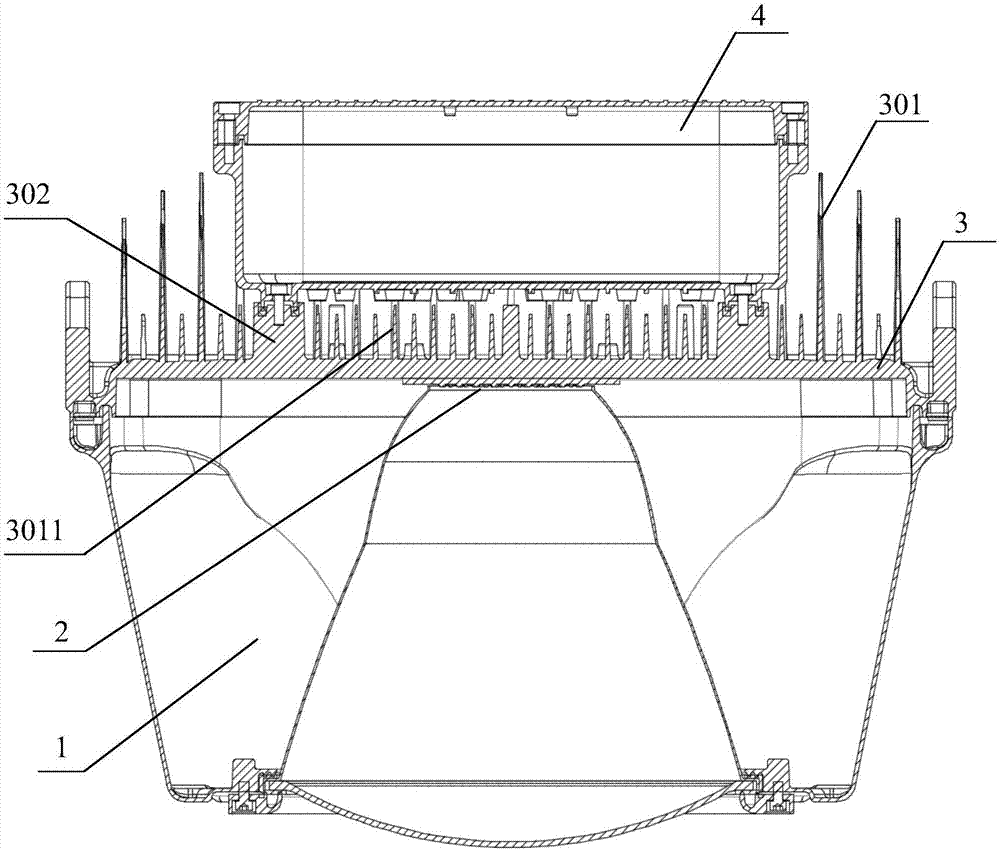
[0047] Such as figure 1 , 2 As shown, the high-power LED lamp with thermally isolated power supply includes a front cover 1, a light source board 2, a heat dissipation housing 3 and a power supply compartment 4 arranged in sequence. The front cover, the light source board and the heat dissipation housing form a light source compartment. The back of the heat dissipation housing is fixedly connected, and the short heat dissipation fins 3011 are located below the power supply compartment.

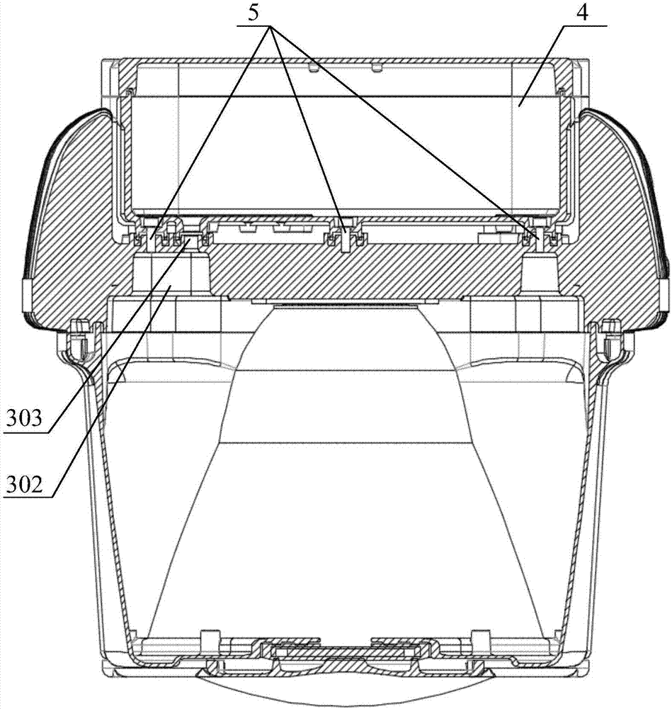
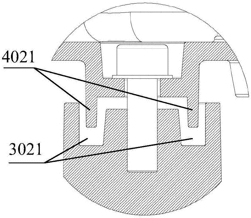
[0048] The power supply compartment 4 is relatively independent from the heat dissipation housing 3 and keeps a distance; the back of the heat dissipation housing forms a group of bosses 302 (usually distributed at four corners) between the heat dissipation fins 301, and the bottom surface of the power supply compartment is connected to the protrusions by a group of ...


PUM


Abstract

The invention provides a power source thermal isolation high-power LED lamp. Safety and reliability of a power source of the high-power LED lamp can be improved, and adverse effects on a power sourcebin due to heat dissipation are lowered. In the power source thermal isolation high-power LED lamp, a front face cover, a light source plate and a heat dissipation shell form a light source bin. The power source bin is fixedly connected with the back of the heat dissipation shell. The power source bin and the heat dissipation shell are relatively independent, and a space is kept. A set of bosses are formed on the back of the heat dissipation shell and between heat dissipation fins. The bottom face of the power source bin is fixedly connected with the set of bosses through a set of screws, a space is kept between the bottom face of the power source bin and the heat dissipation fins below the bottom face of the power source bin, and fixed installation of the power source bin is achieved. Atleast one connecting column is further formed on the back of the heat dissipation shell. The connecting column is provided with a center channel communicating with the light source bin so as to achieve penetrating and connecting of circuits. The bottom face of the power source bin is provided with a connector matched with the connecting column, and a seal thermal isolation rubber ring is arrangedon the joint.

Description

technical field [0001] The invention relates to a high-power LED lamp. Background technique [0002] High-power LED lamps are generally composed of a front cover, a light source board, a heat dissipation shell and a power supply compartment. The power supply compartment is usually based on the empty area on the back of the heat dissipation shell. interface. LED chips generally realize heat dissipation through heat conduction (the connection between the light source board and the heat dissipation housing) and convection (usually the light source board is also provided with air holes to increase air convection). [0003] During the long-term working process of high-power LED lamps, the high heat generated by heat conduction and convection may affect the safety and normal operation of the power supply. In order to reduce the impact of high heat on the power supply, common solutions are: [0004] (1) Increase the distance between the power supply compartment and the cooling f...

Claims


Application Information

Patent Timeline
Patent Type & Authority Applications(China)
IPC IPC(8): F21S9/02F21V23/00F21V29/508F21V31/00F21V29/76F21Y115/10
CPCF21S9/02F21V23/023F21V29/508F21V29/76F21V31/005F21Y2115/10
Inventor 胡家培胡民海
Owner 西安锐泽克斯光电科技有限公司
Why Eureka
Try Eureka