Cylinder head for an air compressor

An air compressor and cylinder head technology, which is applied in the field of cylinder heads, can solve the problems of temperature, rise, etc. that are not raised, and achieve the effects of simplifying the production process, reducing the air volume flow, and reducing the mechanical driving power.

Active Publication Date: 2016-07-20
ZF CV SYST EURO BV
View PDF7 Cites 4 Cited by
  • Summary
  • Abstract
  • Description
  • Claims
  • Application Information

AI Technical Summary

Problems solved by technology

No means are proposed for largely avoiding an increase in the temperature of the ambient air flowing in through the intake air inlet opening

Method used


Image

  • Cylinder head for an air compressor
  • Cylinder head for an air compressor
  • Cylinder head for an air compressor

Examples


Embodiment Construction

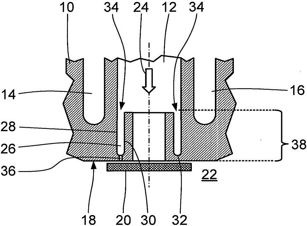
[0023] figure 1 Accordingly, a highly simplified longitudinal sectional view of a first embodiment of the cylinder head 10 according to the invention is shown. The cylinder head has, in particular, an approximately hollow-cylindrical intake channel 12 for drawing in air to be compressed or another gas or gas mixture from the surroundings, two cooling water channels 14, 16 and a pressure channel not shown in the figure, through which The pressure channel conducts compressed air out of the cylinder head 10 . The intake channel 12 can be closed pressure-tight with respect to the compression chamber 22 by means of the suction disc 20 which is movably arranged on the underside 18 of the cylinder head 10 . In this case, the air to be compressed is sucked in from the surroundings through the suction channel 12 in the flow direction 24 indicated by the arrow.

[0024] According to the invention, the suction channel 12 has an annular groove 26 close to the suction blade and surroundi...


PUM


Abstract

The invention relates to a cylinder head (10, 50, 90, 130) for an air compressor, having at least one intake duct (12, 52, 92, 132) for the intake of non-compressed air from the surroundings, and having at least one pressure duct for discharging the compressed air, and also having a cooling water duct (14, 16, 54, 56, 94, 96, 136), wherein the at least one intake duct (12, 52, 92, 132) can be closed off in pressure-tight fashion with respect to a compression chamber (22, 62, 102, 142) by means of at least one intake lamella (20, 60, 100, 140) arranged on an underside (18, 58, 98, 138) of the cylinder head. It is provided according to the invention that the at least one intake duct (12, 52, 92, 132) is surrounded in sections by a substantially concentric annular groove (26, 66, 106, 146) which is close to the intake lamella. In this way, heating of the air flowing out of the surroundings into the cylinder head (10, 50, 90, 130) via the at least one intake duct (12, 52, 92, 132) is advantageously reduced.

Description

technical field [0001] The invention relates to a cylinder head for an air compressor, which has at least one suction channel for intake of uncompressed air from the surrounding environment and at least one pressure channel for discharge of compressed air, and also has a cooling The water channel, wherein at least one suction channel can be closed pressure-tightly against the compression chamber by at least one suction disc arranged on the underside of the cylinder head. Background technique [0002] Compressors for generating compressed air are used in particular for the operation of pneumatic brake systems in motor vehicles and rail vehicles. In order to achieve high efficiency, the ambient air drawn in by the compressor should heat up as little as possible before reaching the compression chamber in the compressor. The heat input into the cylinder head of the compressor is mainly caused by the heat of compression released in the compression chamber. In this case, the str...

Claims


Application Information

Patent Timeline
Patent Type & Authority Applications(China)
IPC IPC(8): F04B39/06F04B39/12
CPCF04B39/06F04B39/064F04B39/125
Inventor 威廉·哈克乌韦·奥珀曼奥利弗·温特
Owner ZF CV SYST EURO BV
Why Eureka
Try Eureka