Quasi progressive lenses for eyewear

a progressive lens and eyewear technology, applied in the field of ophthalmic lenses, can solve the problems of reducing visual quality, eye discomfort, and patient experience loss of image, and achieve the effects of reducing visual experience, reducing visual quality, and gradually increasing optical power in the corridor

Inactive Publication Date: 2015-09-10
SHAMIR OPTICAL IND LTD
View PDF0 Cites 15 Cited by
  • Summary
  • Abstract
  • Description
  • Claims
  • Application Information

AI Technical Summary

Benefits of technology

[0007]Bifocal lenses can correct both far and near vision with the same lens. Bifocal lenses include a first optical zone that provides correction for far or distance vision and a second optical zone that provides correction for near vision. The second zone is usually disposed more nasally in the lower portion of the lens. Bifocal lenses available in the market today have several disadvantages. For example, as the patient's gaze moves from far vision to near vision, a patient can experience loss of image and abrupt jump in the image. Moreover, the transition between the first and second optical zones of available bifocal lenses can have unwanted aberrations that can reduce visual quality and cause vision discomfort. In addition, in many available bifocal lenses, the first and second optical zones may be separated by a visible dividing line, which may be aesthetically unappealing. Furthermore, while bifocal lenses may be able to correct distant and near vision, they may be unable to provide good quality vision at intermediate distances. Progressive lenses can overcome some of the disadvantages of bifocal lenses. For example, many available progressive lenses include a corridor between the first optical zone that provides far or distance vision and the second optical zone that provides near vision. The optical power in the corridor can gradually increase as the gaze moves from far vision to near vision such that objects at intermediate distances between far and near distance can be viewed comfortably through the corridor. However, in some implementations of progressive lenses, the second optical zone providing near vision may occupy a smaller portion of the total area of the lens, which can result in degrading the visual experience associated with viewing objects located at near distances. In some implementations of progressive lenses, the corridor can be long and / or wide. In various embodiments, elongating the corridor may lead to reduced residual cylinder power or aberrations in the first optical zone, the second optical zone and / or in the peripheral zone, while widening the corridor can lead to a strengthening of residual cylinder power or aberrations in these areas. Additionally, in implementations of progressive lenses having long corridors, the patient may have to lower the gaze to such an extent that may be uncomfortable for use when transitioning from far vision state to near vision state and vice-versa.

Problems solved by technology

For example, as the patient's gaze moves from far vision to near vision, a patient can experience loss of image and abrupt jump in the image.
Moreover, the transition between the first and second optical zones of available bifocal lenses can have unwanted aberrations that can reduce visual quality and cause vision discomfort.
In addition, in many available bifocal lenses, the first and second optical zones may be separated by a visible dividing line, which may be aesthetically unappealing.
Furthermore, while bifocal lenses may be able to correct distant and near vision, they may be unable to provide good quality vision at intermediate distances.
However, in some implementations of progressive lenses, the second optical zone providing near vision may occupy a smaller portion of the total area of the lens, which can result in degrading the visual experience associated with viewing objects located at near distances.
Additionally, in implementations of progressive lenses having long corridors, the patient may have to lower the gaze to such an extent that may be uncomfortable for use when transitioning from far vision state to near vision state and vice-versa.
In various implementations of the quasi progressive ophthalmic solution, the transition zone can be optically non-functional such that objects at intermediate distances appear blurred, distorted and / or unclear.
In some instances, objects at intermediate distances cannot be resolved when viewed through the optically non-functional transition zone.

Method used


Image

  • Quasi progressive lenses for eyewear
  • Quasi progressive lenses for eyewear
  • Quasi progressive lenses for eyewear

Examples


Embodiment Construction

[0138]It is to be understood that the figures and descriptions of the present invention have been simplified to illustrate elements that are relevant for a clear understanding of the present invention, while eliminating, for the purpose of clarity, many other elements found in typical lenses, lens design and / or manufacturing methods, and eyewear. Those of ordinary skill in the arts can recognize that other elements and / or steps are desirable and may be used in implementing the embodiments described herein.

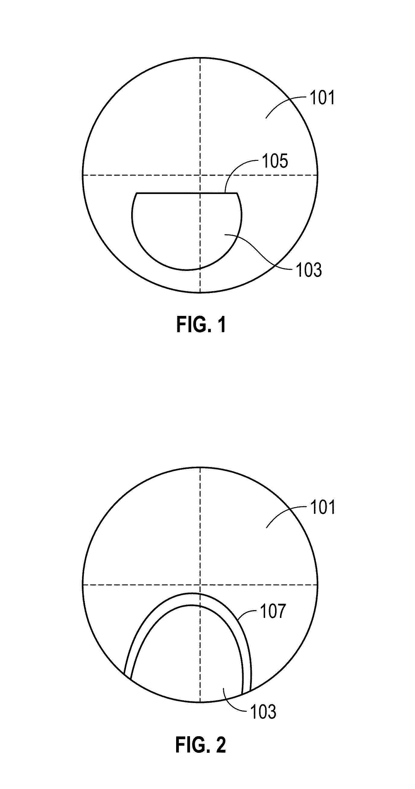
[0139]As used herein, the term “fitting point” may indicate a point on a lens as mounted in a spectacle frame, aligned with the patient's center of the pupil in its distance viewing position when the patient is looking straight ahead.

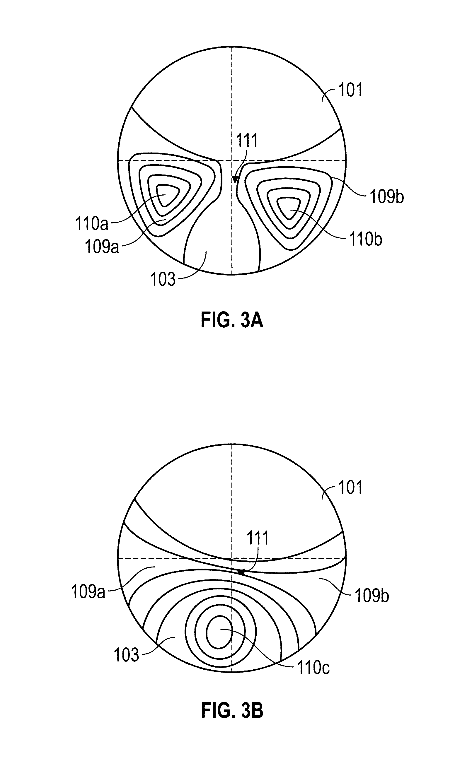
[0140]The term “clean” used in reference with an optical zone or area including a powered surface indicates that optical zone or area has residual cylinder power or aberrations below a threshold (e.g., less than 1.0 Diopter, less than 0.75 Diopter, les...


PUM


Abstract

Various embodiments disclose a quasi progressive lens including a first optical zone capable of providing distance vision, a second optical zone capable of providing near vision and a transition zone connecting the first and second optical zones. Physical dimensions (e.g., length and width) of the transition zone are adjusted to increase the size of the second optical zone in comparison to progressive lenses and to reduce residual cylinder power and aberrations along the convergence path in comparison to bifocal lenses.

Description

CROSS-REFERENCE TO RELATED APPLICATIONS[0001]This application claims benefit under 35 U.S.C. §119(e) of U.S. Provisional Application No. 61 / 971,469, filed on Mar. 27, 2014, titled “Quasi Progressive.” This application also claims benefit under 35 U.S.C. §119(e) of U.S. Provisional Application No. 61 / 938,029, filed on Feb. 10, 2014, titled “BIFOCAL LENS,” and U.S. Provisional Application No. 61 / 991,420 filed on May 9, 2014, titled “QUASI BI-PRISM LENSES AND MULTI SEGMENT LENSES FOR EYEWEAR.” The disclosure of each of the above identified applications is incorporated by reference herein in its entirety.BACKGROUND OF THE INVENTION[0002]1. Field of the Invention[0003]This description relates generally to ophthalmic lenses used in eyewear that provide near vision as well as distance vision correction as well as lenses that provide prismatic correction.[0004]2. Description of the Related Art[0005]Refractive errors are the most frequent eye problems encountered by patients of all ages. Ref...

Claims


Application Information

Patent Timeline
Patent Type & Authority Applications(United States)
IPC IPC(8): G02C7/06G02C7/14
CPCG02C7/14G02C7/066G02B3/10G02C7/06G02C7/063
Inventor CARMON, YUVALGIL, YOTAMGLESER, LIRONSHUR, ALEX
Owner SHAMIR OPTICAL IND LTD
Why Eureka
Try Eureka