Self-cleaning filter

a filter and self-cleaning technology, applied in the field of hydraulic valves, can solve the problems of affecting the operation of the valve, and the most frequent failure of the typical hydraulic system, and achieve the effects of reducing the number of filters, ensuring the cleanliness of the fluid, and ensuring the cleanliness of the filter

Active Publication Date: 2006-11-21
US BANK N A
View PDF14 Cites 16 Cited by
  • Summary
  • Abstract
  • Description
  • Claims
  • Application Information

AI Technical Summary

Benefits of technology

[0008]The invention provides an effective and durable filter for two-stage hydraulic valves. The invention may also be usefully applied in other types of valves or in other types of devices when cleanliness of the fluid is desired and space is limited.

Problems solved by technology

Hard small particles, collectively called “contamination,” are among the most frequent cause of failures in typical hydraulic systems.
If the orifice is exposed to contamination, then the particles that make up the contamination may not pass through and, eventually, may block the orifice.
A blocked orifice is a common cause of valve failure or hydraulic system failure.
Existing “in-valve” filters are not very effective, however.
Furthermore, existing in-valve filters tend to be expensive.
However, in some applications, filters with large open areas are not practical because of space constraints.
However, the latter type of filter has its own drawbacks, which are most evident in high-pressure applications.
One drawback is that the filter element is structurally weak and requires additional support to withstand differential pressure force when the filter is clogged with debris.
Another drawback of small, highly open filters is that they tend to permit large particles to enter.

Method used


Image

  • Self-cleaning filter
  • Self-cleaning filter
  • Self-cleaning filter

Examples


Embodiment Construction

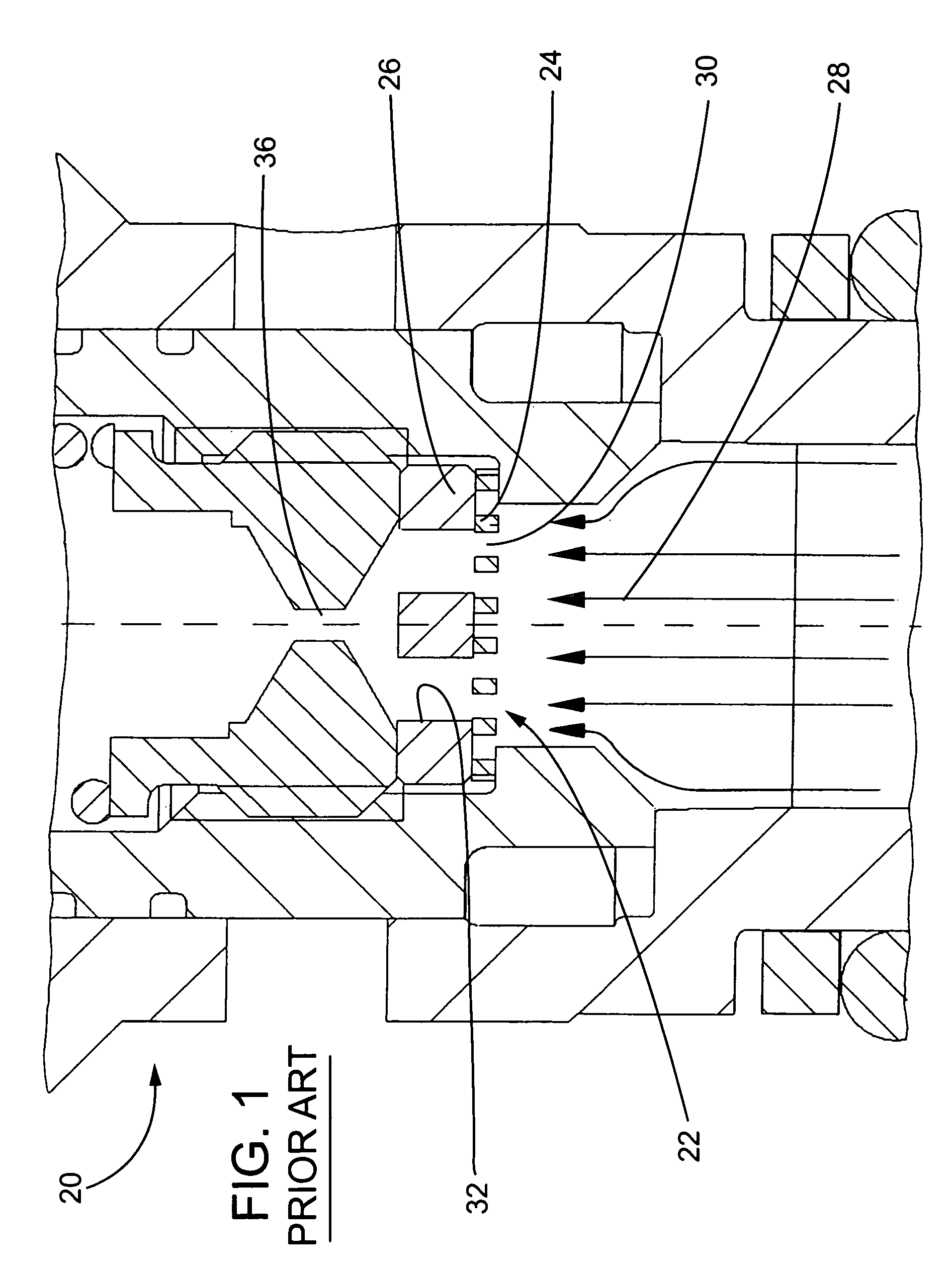
[0028]Referring to FIG. 1, a typical prior art valve 20 is shown. The valve 20 includes a filter assembly 22 with a perforated screen disk 24 and an additional support disk 26. A flow 28 of fluid entering the filter assembly 22 can pass through a plurality of passage openings 30 in the screen disk 24 and openings 32 of the support disk 26, which are relatively larger than the passage openings 30 of the screen disk 24, to a pilot orifice 36.

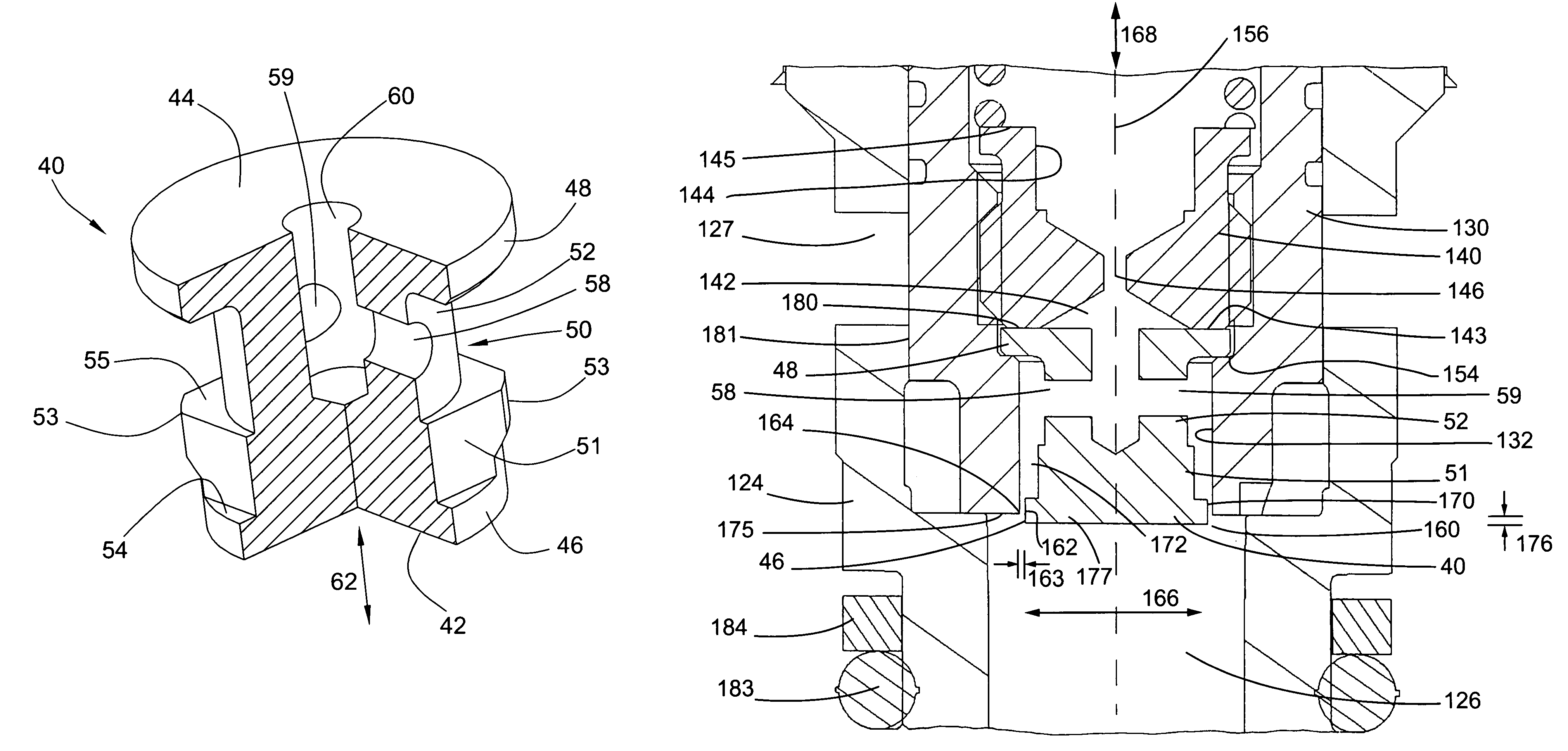
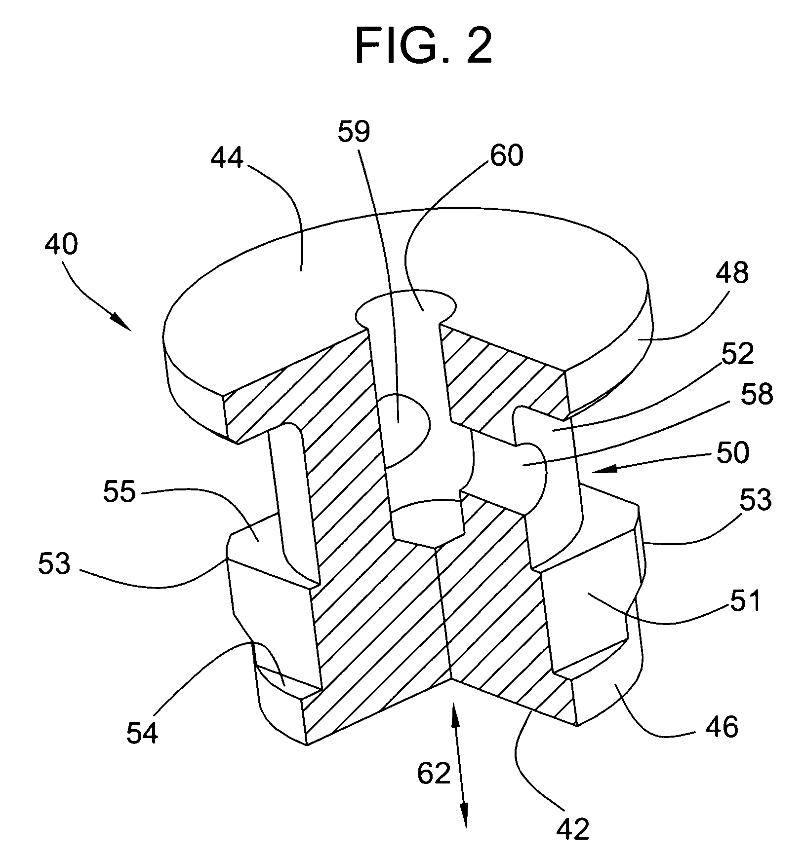
[0029]Referring to FIG. 2, an embodiment of a filter 40 according to the present invention is shown. The filter 40 is generally cylindrical. The filter 40 can include an entrance end 42 and an exit end 44 with the entrance end having an entrance head in the form of a passage flange 46 and the exit end having a mounting flange 48. The flanges 46, 48 are generally circular. A body portion 50 of the filter includes first and second sections 51, 52 which have different shapes from each other. The first section 51 is generally square-shaped, including ...


PUM

PropertyMeasurementUnit
sizeaaaaaaaaaa
lengthaaaaaaaaaa
offset distanceaaaaaaaaaa

Abstract

A self-cleaning filter for use in a valve is disclosed. The valve can include a bore, an orifice disposed in the bore for accommodating a fluid flow therethrough, and a filter disposed in the bore between the input port of the fluid flow being filtered and the orifice being protected. The filter can include an entrance head in predetermined spaced relationship with the bore of the valve to define a filter entrance and a body portion. The entrance head can be configured to prevent particles of a predetermined size from entering the filter entrance. The body portion can include at least a portion that has a different shape than the entrance head which cooperates with the bore to define a fluid passage. The fluid passage can have an exit port which is communicable with the orifice to send filtered fluid to the orifice. The filter can include an offset portion which extends beyond an end face of the bore which is useful to develop pressure gradients which provide for a self-cleaning function. In some embodiments, the filter can include an integral orifice.

Description

CROSS-REFERENCE TO RELATED PATENT APPLICATIONS[0001]This patent application claims the benefit of priority to U.S. Provisional Application No. 60 / 427,483, filed Nov. 19, 2002, entitled “Self Cleaning Filter,” which is incorporated in its entirety herein by this reference.FIELD OF THE INVENTION[0002]The present invention relates generally to hydraulic valves, and, more particularly, to valves with small flow passages that require protection from contaminate particles carried by fluid.BACKGROUND OF THE INVENTION[0003]Hard small particles, collectively called “contamination,” are among the most frequent cause of failures in typical hydraulic systems. Contamination is carried by the fluid flowing through the hydraulic system, penetrating virtually every flow passage. To combat this problem, a typical hydraulic system is equipped with a replaceable low-pressure filter that is usually located in the return-to-tank line at the end of the entire hydraulic circuit. The filter's role is to se...

Claims


Application Information

Patent Timeline
Patent Type & Authority Patents(United States)
IPC IPC(8): B01D29/00F16K31/40B01D46/24
CPCB01D46/005B01D46/24F16K31/406B01D2275/206Y10T137/794
Inventor SLAWINSKI, TOMASZKAZAK, VALERIY
Owner US BANK N A
Why Eureka
Try Eureka